
ART1751S ART2346
Sound effects are always attractive, especially for those who play an instrument, have musical groups, or like to enjoy sound in a different way. There are some effects, in particular, that are quite simple to assemble, such as this tremolo that uses only 3 transistors and is powered by common batteries. Placed between a signal source and the power amplifier, this circuit modulates the sound to cause rapid variations in an infrasonic frequency, which results in the "trembling" reproduction that gives rise to its name.
The assembly of the device is quite simple, and the only critical point is the use of shielded wires at the inputs and outputs to avoid picking up hum, since we are working with low-intensity audio signals that are subject to significant amplification. All components are common in our market, and the device has only two controls.
THE CIRCUIT
A high-gain, low-noise transistor is used as a variable-gain amplifier. This transistor is Q1, which has a modulation signal application network in its base bias, highlighting P1, which controls the depth of the effect. With the application of the signal, a low-frequency sine wave (between 0.1 and 10 Hz), the transistor's gain changes, and with it the amplitude at the output. We then obtain the intensity variations that characterize the effect.
The low-frequency sine wave is obtained through a phase-shift oscillator with two transistors (02 and 03), and its frequency is determined by both the feedback capacitors and the associated resistors. By making one of the resistors adjustable, we can fix the frequency according to the type of effect we want. The circuit is powered by a 6V voltage, which can be obtained from 4 small batteries, since the unit's current consumption is quite low. If a power supply is used, it must have excellent filtering so that ripple does not produce hum in the sound reproduction.
ASSEMBLY
Figure 1 shows the complete circuit of the device.
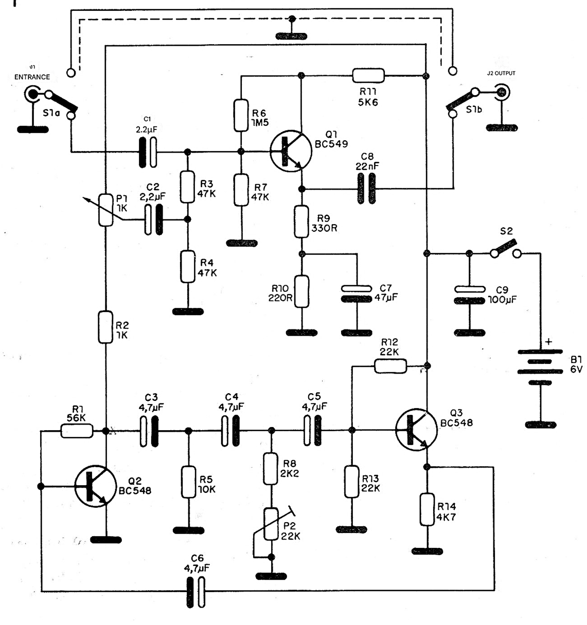
Switch S2 is used to switch the effect, turning it off and allowing the signal to pass directly from the source to the amplifier.
The printed circuit board is shown in Figure 2.
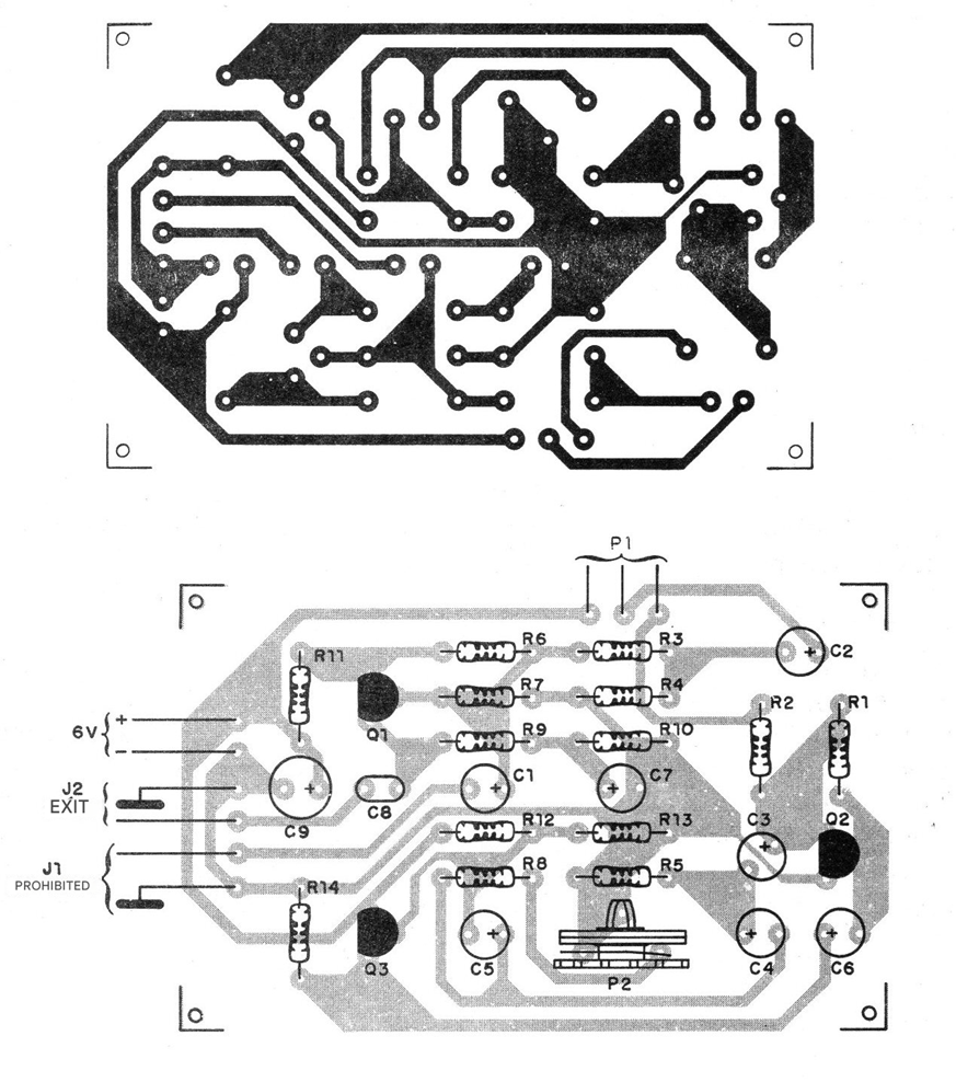
Note that both the input and output signal cables are shielded, with the shields properly interconnected and connected to the negative of the source, so that hum does not occur. The resistors are all 1/8 or ¼ W. P1 is a potentiometer that controls the depth of the effect, while P2 can be a trimpot. The electrolytic capacitors must have a working voltage of at least 6 V, and C8, the only non-electrolytic capacitor can be ceramic or polyester, with a working voltage of at least 25 V. For the inputs and outputs, jacks and plugs should be used according to the instrument and the amplifier input.
TESTING AND USE
This circuit should be inserted between instruments (acoustic or electric guitars), turntables or tape decks and the input of amplifiers or preamplifiers. Do not apply signals from the output of amplifiers to its input, nor attempt to connect speakers or low-impedance devices to its output, as this may cause strong signal distortion. After connecting the instrument or signal source and the amplifier, adjust them and act on P1 to obtain the desired effect. If the effect does not occur, check the oscillation of Q1 and Q2 using a multimeter connected to the emitter of Q3. An oscillation of the needle should be observed. If this does not occur, check the transistors and components associated with the oscillator, as well as the adjustment of P2.
List of Materials
Q1 - BC549 or equivalent - low-noise NPN transistor
Q2, Q3 - BC548 or equivalent general-purpose NPN transistors
P1 – 1 kΩ - potentiometer
P2 – 22 kΩ - trimpot
R1 – 56 kΩ x 1/8 W - resistor (green, blue, orange)
R2 – 1 kΩ x 1/8 W - resistor (brown, black, red)
R3, R4, R7 – 47 kΩ x 1/8 W – resistors (yellow, violet, orange)
R5 – 10 kΩ x 1/8 W - resistor (brown, black, orange)
R6 - 1.5 MΩ x 1/8 W - resistor (brown, green, green)
R8 - 2.2 kΩ x 1/8 W - resistor (red, red, red)
R9 - 330 ohms x 1/8 W - resistor (orange, orange, brown)
R10 - 220 ohms x 1/8 W – resistor (red, red, brown)
R11 - 5.6K ohm x 1/8 W - resistor (green, blue, red)
R12, R13 – 22k ohm x 1/8 W – resistors (red, red, orange)
R14 - 4.7k ohm x 1/8 W - resistor (yellow, violet, red)
C1, C2 - 2.2 uF x 6 V – electrolytic capacitors
C3, C4, C5, C6 - 4.7 uF x 6 V - electrolytic capacitors
C7 - 47 uF x 6 V - electrolytic capacitor
C8 – 22 nF - ceramic or polyester capacitor
C9 – 100 uF x 6 V - electrolytic capacitor
S1 - 2-pole x 2-position switch
S2 - simple switch B1 – 6 V - 4 batteries Small jacks
J1, J2 - input and output jacks according to the sound equipment and instrument used
Miscellaneous: printed circuit board, mounting box, holder for 4 small batteries, shielded wires, knob for the potentiometer, wires, solder, etc.


