
ART2192S ART2264
The typical magnetic sensor is formed by a reed switch, which can be activated by a magnetic field. The magnetic field can be produced by a coil or by a magnet. Figure 1 shows the structure of a typical sensor for use in alarms like the one we propose in our systems.
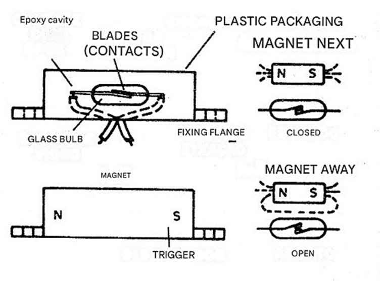
The reed switch inside one of the parts keeps its contacts closed when the magnet is nearby. The magnet is attached to any movable object that could be displaced by an intruder, such as a door or window.
When the magnet is moved away, the switch opens because its reeds separate. Figure 2 shows another type of magnetic sensor where the magnet acts from a different position.

The two types of sensors can be used for protection in various ways, shown in Figure 3.
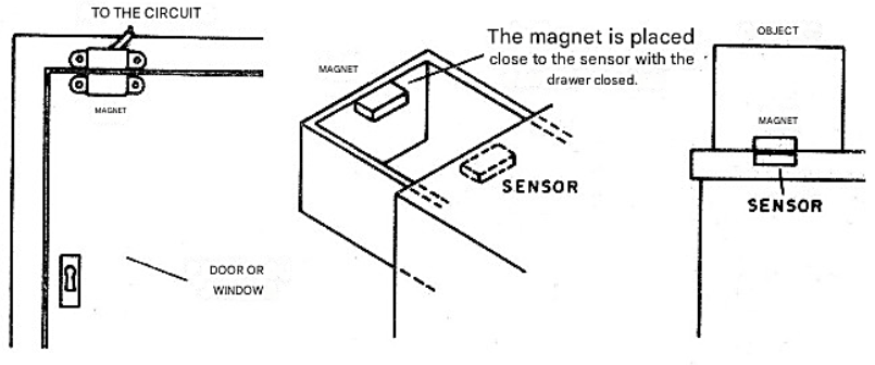
Thus, for doors, windows, and trapdoors, simply attach the reed switch to the side of these objects and the magnet to the moving part. When the door, window, or trapdoor is closed, the switchblades will remain in contact, closing the electrical circuit.
Moving the magnet away opens the circuit. To protect an object, simply attach the magnet to this object and place the sensor in the appropriate position. Moving the object away removes the magnet, and thus the switch has its contacts opened.
For the protection of only one point, simply connect a pair of wires directly from the sensor to the alarm system, as shown in Figure 4, but in the case of protecting several points, we must connect each sensor, as shown in the same figure.
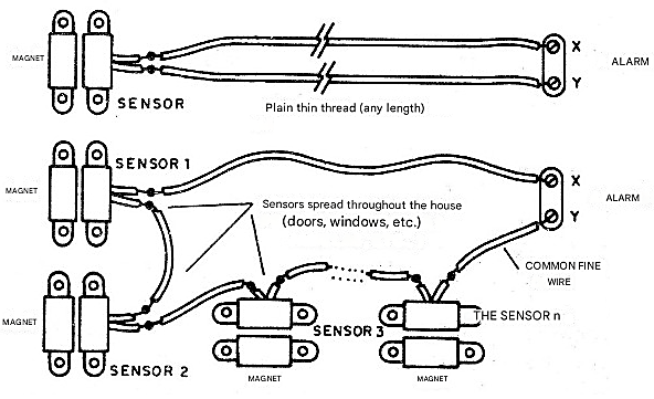
We then have the so-called series connection, in which the current must pass through all the sensors.
The opening of any of them interrupts the current in the circuit and triggers the alarm. The contacts of the reed switches used in these sensors are not designed to withstand high currents.
This means they should operate with low-intensity currents and not with the currents that control warning systems such as sirens or buzzers. Thus, systems that use these sensors are designed to operate with very weak, usually continuous, currents. This means that thin wires can be used to interconnect the sensors, which is useful if we want to hide these wires in an installation.
We can use 22AWG wires, or even thinner ones, with plastic sheathing for the connections, and their length is practically unlimited, only needing to not exceed a 1 km circuit. The systems we propose below have a wide variety of characteristics, which should be analyzed so that you can make the ideal choice. An important fact to consider is that the characteristics of all systems are matched, that is, they allow a combination of designs to form a single, more or less sophisticated system.
TOTAL ALARM WITH LOW POWER WARNING SYSTEM
This is a simple system, ideal for protecting objects, drawers and small environments, as it already has an audio oscillator that can be heard a few meters away.
Its main features are:
• 6 or 12V power supply with batteries
• Built-in warning circuit
• Can be used with a magnetic sensor
• No timer (triggers when the sensor is opened)
Figure 5 shows the complete circuit of this alarm.
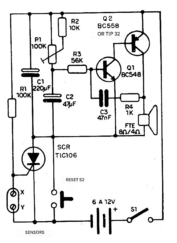
The quiescent current is very low, meaning it can remain on for weeks without the batteries wearing out. When the sensor is opened (one or more of them), the SCR triggers and powers the audio oscillator, whose sound is adjusted by P1. The power is around 0.5 W for a 6 V supply and can reach 1 W with a 12 V supply.
With 12 V, it will be necessary to replace transistor Q2 with a TlP32, equipped with a small heat sink. Once this alarm is triggered, even if the magnet is brought closer to the sensors again in an attempt to inhibit the system's action, nothing happens. To reset the system, it is necessary to press S2 shortly (with the sensor placed back next to the magnet). If S2 is not pressed, the system will emit sound until the batteries run out.
Figure 6 shows the suggested installation of the system in drawers and objects for local protection in shops or offices.
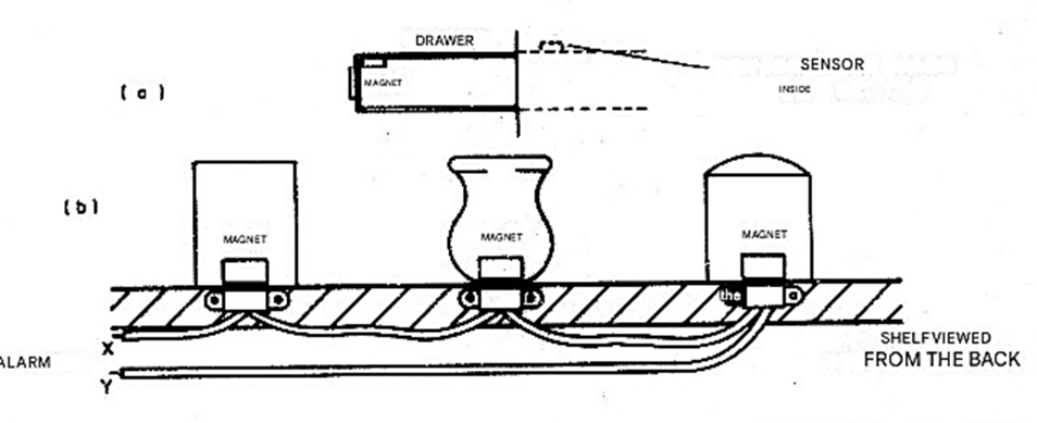
In the case of drawer protection (a), the alarm will sound if any drawer, or one specifically, is opened. In (b) we have the triggering if an object is removed from its location, which is an interesting suggestion for stores.
ALARM WITH LOCK FOR RESIDENCE – VERSION I
This basic circuit triggers when any of the sensors connected to inputs X and Y are opened, with no limit to their quantity. The warning system will be connected at points A and B, and the battery charger to points C and D. The charger and the system will be suggested later in this article. As we can see from the diagram in Figure 7, the alarm triggers a relay, activating the power warning system as desired.
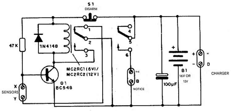
To power the system we can use 6 or 12 V motorcycle or car batteries, which will be kept in permanent recharge by an external charger.
The features of this alarm are:
• Unlimited number of sensors
• Locking mechanism
• Power supply via 6 or 12 V battery
• Unlimited power for the warning system
As we can see, the circuit is based on a transistor, which remains cut off when the sensors have their contacts closed. The opening of any sensor brings the transistor close to saturation, activating the relay.
Contacts 8 and 9 of the relay can be used to power a warning system from the local 110 or 220 V mains. The relay used has a maximum contact current of 2 A. To reset the system after it has been triggered, it is necessary to replace the magnet near the open sensor and shortly press switch S2, which is a normally closed type (refrigerator door switch).
HOME ALARM WITH LOCK USING SCR - VERSION 2
This circuit (Figure 8) is suitable for protecting homes, offices, and medium-sized commercial establishments, operating with an unlimited number of sensors and a 12V battery, which remains permanently charged if a charger is used between points C and D.
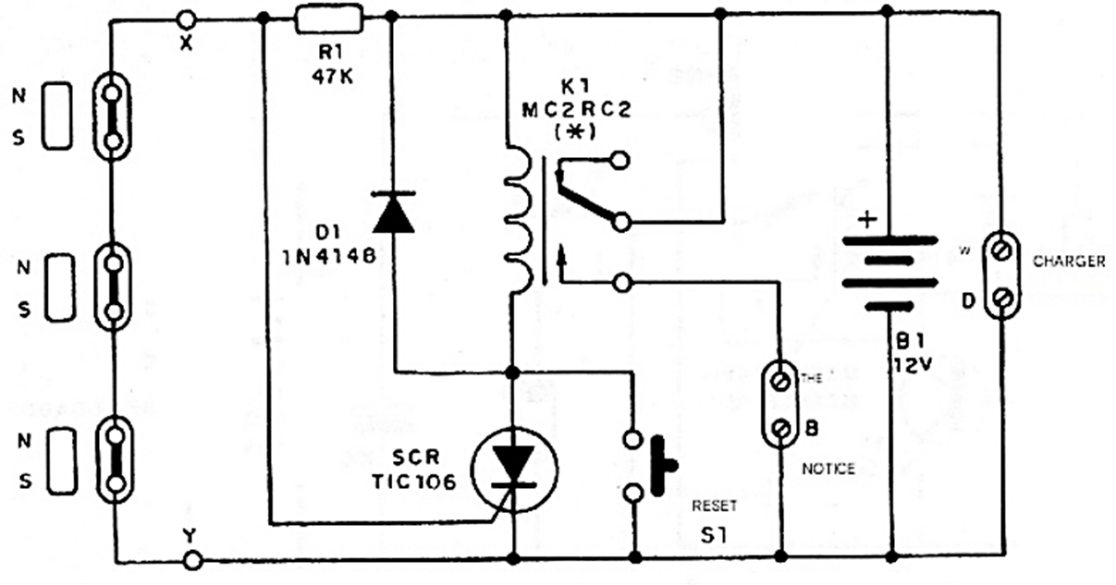
The system locks when the sensors are activated, meaning that it is not possible to stop the alarm from sounding simply by bringing the magnet close to the activated sensor again.
The main features of this alarm are:
• 12V battery for power supply
• Charger can be used
• Unlimited number of sensors
• Has a lock
In this circuit, we must observe that there is a small voltage drop of 2V in the SCR when conducting.
Most 12V relays normally close with 2V less, but if that is not enough in your case, we suggest replacing the relay with a 6V relay with a 479 x ½ W resistor connected in series.
GENERAL PURPOSE TIMED ALARM
The circuit shown in Figure 9 has an important feature for those who often leave home for extended periods.
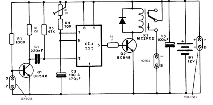
Once triggered, the alarm's activation time is adjustable between a few minutes and more than half an hour. In this way, if there is no possibility of someone intervening, calling for help or entering the house to disarm the alarm, once the intruder has been driven away, it deactivates after some time, not producing noise until the battery runs out, which can take many hours.
The operating principle of this circuit can be explained as follows: with the opening of any of the sensors, transistor Q1 conducts, shortly grounding pin 2 of a 555 monostable multivibrator. This momentary grounding is sufficient to trigger the monostable multivibrator for a time given by C2 and the adjustment of P1.
C2 can have values up to 1000 uF, although above 470 uF we should use a capacitor of excellent quality, without leakage. The potentiometer should also not be much larger than 1MΩ to avoid instability problems.
The actuation time is given by the formula:
T = 1.1 x R x C
Where:
R is the total resistance given by R4 and P1, and C is the value of the capacitor, in farads. The output of the 555 acts on a transistor, which closes the relay that controls an external load.
The characteristics of this circuit are:
• Timing up to more than half an hour
• 12V power supply
• Unlimited number of sensor
• Allows the use of a charger
To reset this alarm, simply reconnect the open sensors, bringing the magnets closer together, and momentarily disconnect the power supply or the warning system, waiting for the relay to open its contacts.
DELAYED ALARM
The circuit shown in Figure 10 has a timed trigger, that is, it only comes into action a few seconds after the sensor is activated.
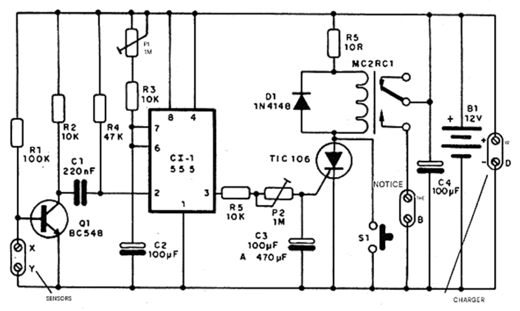
From a strategic point of view, this can be very interesting because it allows you to catch the intruder by surprise only after he is already in possession of the targeted object or inside the residence, where he can be surrounded.
The characteristics of this system are:
• Timer for triggering
• Unlimited number of sensors
• 12V power supply
• Allows the use of a charger
The system starts operating when any sensor is opened and transistor Q1 is biased so as to momentarily ground the input of the 555 monostable multivibrator, which has its output raised to a high level for a time given approximately by:
t = 1.1 x R x C
Where R is given by the sum of P1 and R3, and C is given by C2. The time adjusted by P1 must be greater than the time constant of the output (pin 3) that triggers the SCR. In this way, with the integrated circuit output at a high level, C3 charges slowly until the SCR triggers.
With the triggering, the relay has its contacts closed and acts on the external warning system. Even after the sensor connections are re-established (magnet proximity) and the 555 returns to its low output level, the alarm remains activated. To reset, it will be necessary to press the push-button switch S1 shortly.
The resistor R5 can have values between 10 and 47 ohms, being necessary to obtain a lower voltage across the 6V relay, since the 12V types may not trigger considering a voltage drop of 2V in a fully conducting SCR. Capacitor C3 should be sized to obtain a delay time of approximately 5 to 15 seconds, depending on the adjustment of P1 and P2.
BATTERY CHARGER
Lead-acid alarm batteries, whether for cars or motorcycles, are charged by circulating a current from a power source. The ideal charger consists of a constant current source. In this application, however, since we have a slow charge, a less sophisticated version is perfectly acceptable and suitable for the proposed types. The circuit of a first source used as a battery charger is shown in Figure 11.
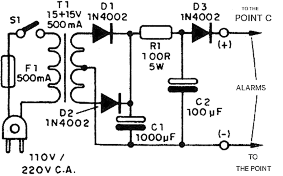
The primary winding of the transformer is according to the local mains voltage, and the secondary is 15 + 15 V with 500 mA or more of current. The capacitor C1 must have a working voltage of 25 V or more and the resistor R1, which determines the intensity of the charging current, is wire-wound.
The diode D2 serves to prevent the return of current from the battery to the source when there is a power cut. Capacitor C2 also has a working voltage of 25 V and the protection fuse is 500 mA. This power supply can be mounted in a separate box from the alarm system or in the same box. Its positive (+) terminal is connected to point C of each alarm and the negative (0 V) to point D.
STABILIZED POWER SUPPLY WITH POWER FAILURE ALARM
Considering the possibility of an intruder cutting off power to a location, and anticipating the activation of alarms, Figure 12 shows a second, more sophisticated power supply that incorporates a system that triggers an alert when a power outage occurs.
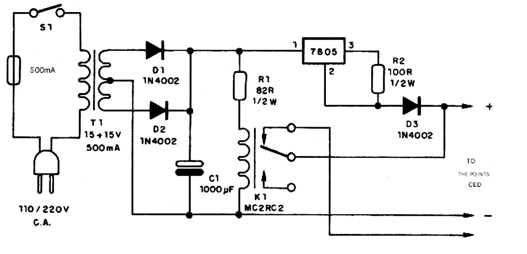
The power supply is a constant current type, for slow charging of approximately 50 mA (provided by resistor R2), and uses a 7805 integrated circuit as its base, which should be mounted on a small heat sink. The transformer has a primary winding according to the local mains voltage and a secondary winding of 15+15 V with at least 500 mA of current. The diodes are of the 1N4002 type or equivalent higher voltage type.
The relay is 12 V and has a limiting resistor because, after rectification and filtering, the power supply provides approximately 22 V at the integrated circuit input. The connection points for this power supply are shown in the diagram.
Note that, under load conditions, the relay remains energized, which corresponds to a switch in parallel with the alarm relay, but open. If there is a power outage, the relay is de-energized and causes the warning system circuit to close. The operating voltage of C1 is 25 V and the two resistors are ½ W.
POWERFUL WARNING SYSTEM
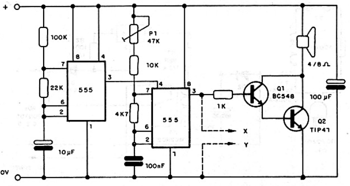
The warning system proposed in Figure 13 is suitable for all alarms described in this article, except for the one with its own oscillator.
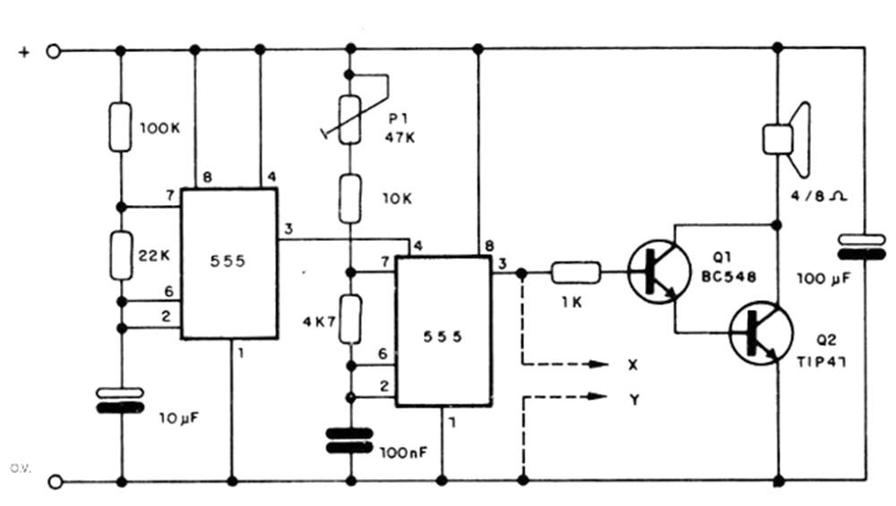
This modulated siren produces intermittent beeps with good amplification through two transistors in a Darlington configuration. With a 12V power supply, we have a few watts of power, and transistor Q2 should be equipped with a heat sink. The speaker should be of good efficiency, preferably installed in a small acoustic enclosure.
We suggest using a speaker of at least 10 cm with 4 or 8 ohms impedance. If you prefer, you can use a higher power stage, such as an audio amplifier, with its input connected to points X and Y.
The only adjustment in this circuit is given by P1, which determines the tone of the emitted beeps. This circuit can be powered by either 6V or 12V, and the resistors are all 1/8W. The electrolytic capacitor is 12V, and the 100nF capacitor can be either polyester or ceramic.
TIMED DISARM
A common problem that can occur when installing a security system is how to leave and have the system rearm itself, and then, upon returning, how to enter and have it disarm long enough for you to deactivate it? The circuit shown in Figure 14 is a timed disarm, which is quite interesting because it also uses a magnetic sensor that must be hidden in a place accessible from the outside and known only to you.
By bringing a magnet (which can be carried with a keychain) close to the sensor, the alarm will be disarmed long enough for you to enter the house and deactivate the system. When we bring the magnet close to the sensor, pin 2 of the 555 is grounded momentarily, triggering the monostable multivibrator which will then maintain its output at a high level for a time determined by R2 and C1 (for longer times, increase C1).
With the output at a high level, Q1 is saturating, energizing the relay, which then inhibits the action of the alarm system sensors. During this disarming interval, we can open any of the protection system sensors without triggering them.
Using this system at the exit is simple: before activating the alarm system, briefly bring the magnet close to the disarming sensor. After that, you will have a few minutes to turn on the system and leave. After the interval given by C1 and R2, the sensors return to standby mode and can be used normally when objects, doors, and windows are opened.
The disarming system is powered by the alarm's own battery, connected to points G and H of the circuit. The inhibition system is connected from points E and F to points X and Y of the alarms.
JOINT CONNECTION
Alarms, warning systems, chargers, and timed disarms should be connected as shown in Figure 15.
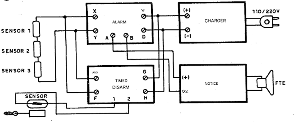
Of course, in a simpler version, both the disarm and the charger can be eliminated. The connecting wires of the various units are common. Only the sensor wires can be very thin, which would facilitate their concealment. Another wire that can be very thin is that of the disarm sensor, which would also facilitate its installation.
Options for more powerful warning systems can be made based on powerful relays, for activating car horns or sirens, as well as for activating devices powered by the local network (although in the case of a power outage, it does not activate). Figure 16 shows the case of activating a high-power auxiliary relay for a horn.
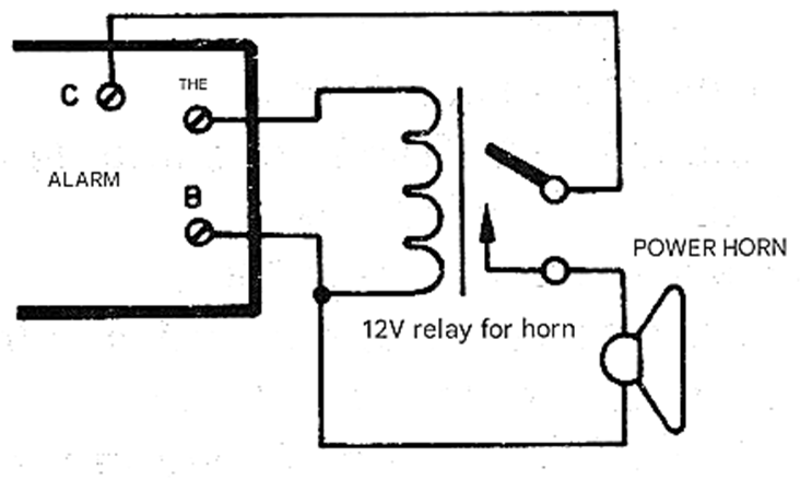
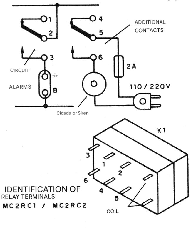
Figure 17 shows the connections for a parallel warning system that acts on an industrial siren or even a high-power buzzer.
CONCLUSION
There are many possible variations around the same proposed circuits, including parallel activation by other types of sensors. Touch, proximity, light or fire detection systems can be added to a more elaborate system, but that will be a topic for another time. The use of sensors in applications other than alarms will also be addressed at another time.
Machine limit switches, position indicators, wind direction indicators, buoy activation, and various automation systems can perfectly be developed based on the magnetic sensors described in this article.


