
ART1753S ART2349
Note: This article is from the book "Playful Experiments with Electronics – Volume 7," whose original edition is from 1980. However, the project can still be assembled with common components.
Many people like to enhance their sound systems by connecting LEDs (Light Emitting Diodes) to the output of their amplifiers. These are small electronic devices that light up when a current passes through them, thus acting as lamps. Connected directly to the speaker outputs, these LEDs follow the rhythm of the music, creating a very interesting effect of rhythmic mini-lights.
However, connecting the LEDs directly to the amplifier output presents serious drawbacks. Firstly, the LEDs, being sensitive to reverse power surges, can burn out extremely easily if they lack any protection device.
The second issue is that the LED "steals" power from the amplifier, as it lights up with the current that should be converted into sound and instead converts to light. If the number of LEDs is large, in addition to stealing a good portion of the amplifier's power, we also run the risk of overloading the amplifier's output stage, potentially damaging its components.
The rhythmic LED project we present does not have all these drawbacks.
Having its power supply separate from the amplifier, it allows for a huge number of LEDs (up to 50!) without any problem of overloading the amplifier.
In fact, the circuit only needs 0.001W to operate, which means that even a portable radio with 2 batteries can make all 50 LEDs blink! This feature is important considering that we do not need to fear any loss of amplifier volume or damage to its components. The system is completely isolated from the amplifier and works with any output power!
The second positive aspect of the project lies in the brightness achieved for the LEDs, which is independent of the amplifier's power. They all light up brightly with the sound, yet are fully protected against overloads or reverse polarity, guaranteeing complete operational safety for the device.
As readers will see, assembling this rhythmic LED system is extremely simple, using few low-cost components. Even readers with less experience can successfully complete this assembly.
HOW IT WORKS
What we have here is a conventional rhythmic light system where the power supply of a common incandescent lamp is replaced by a series of LEDs.
Since LEDs have a completely different electrical behavior from a common lamp, it is precisely with this component that we begin our analysis of the circuit's operating principle.
Figure 1 shows the symbol and appearance of a common LED.
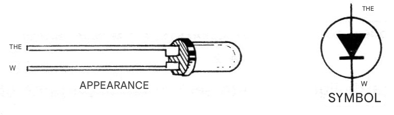
It is a semiconductor device, that is, an electronic device that uses semiconductor materials that are responsible for its electrical properties. We then have a gallium arsenide (GaAs) crystal that, when traversed by a current, emits light, exactly like a common lamp.
The type of material used and its impurities determine the color of the emitted light. The most common are those that emit red light and are consequently the cheapest. Slightly more expensive are LEDs that emit green and yellow light.
Note: At the time, LEDs were still a novelty, and the low-cost types that are common today were not available. Thus, LEDs in colors up to blue and violet can be found today, which was not the case when the book was written.
The electrical behavior of an LED, however, is quite different from what would be expected of a common light bulb. Common light bulbs light up regardless of the direction of the current flowing through them; that is, they have no polarity for connection, as shown in Figure 2.
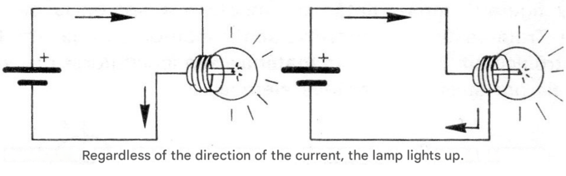
LEDs, on the other hand, only light up when the current flows in one direction, and if this current is forced to flow in the opposite direction, they will burn out. Hence, the need for a well-planned power supply.
To prevent the LED from burning out due to excessive current, if the voltage supplying it is above a certain value, a resistor of appropriate value must be connected in series with it. Figure 3 shows a power supply circuit for an LED with two batteries and a current-limiting resistor.
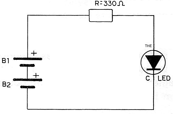
Note that if we connect an LED directly to two batteries, it will burn out immediately because there is no current limiter. Therefore, do not attempt to test your LEDs by connecting them to batteries or other power sources without having a resistor of appropriate value in series.
When connecting the LED to the circuit, it is very important to observe its polarity so that the current flows correctly and it functions properly. Returning now to our circuit, we can make a block diagram to explain its operation in its entirety. This diagram is shown in Figure 4.
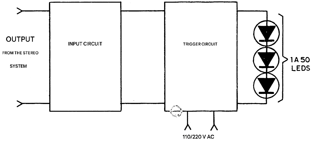
We then have an input circuit that, from a small portion (0.001W) of power from its amplifier, triggers a second circuit, called the power circuit, which will light the LEDs. The input circuit has a transformer that isolates the amplifier from the power supply that will power the LEDs. This transformer is most important because it represents isolation between the amplifier and the LED power supply circuit. It therefore protects the amplifier against any problems that may occur with the rhythmic circuit. The trigger circuit has as its basic component an SCR (Silicon Controlled Reflectance), whose symbol and basic connection are shown in Figure 5.
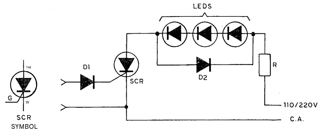
When powered by alternating current, such as that supplied by 110V and 220V mains, the SCR turns on when excited by a small signal applied to its gate and turns off when the signal disappears.
If the signal is variable, as is the case with those coming from the amplifier via a transformer, the SCR will turn on and off following these variations, which are precisely due to the sounds being reproduced. Any device connected to the SCR will turn on and off following the rhythm of the music.
As we have already seen, an important characteristic of this circuit is that the power the SCR needs to turn on is extremely small, which means that the amplifier does not suffer any overload. The problem of connecting LEDs to the SCR must be carefully analyzed.
First, we must consider that LEDs have a specific polarity for the current that lights them up, and that if there is a reversal, they may burn out. Secondly, we must remember that current limiting should be done using an external resistor, and once correctly calculated, we do not need to worry about the circuit voltage (even if it is 110 or 220 V). Thus, Figure 6 shows the connection of the LEDs to the SCR, in this case only 5, with no circuit modifications even with up to 20 LEDs.
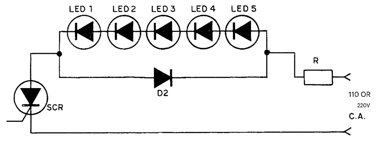
For values greater than 20 ohms, the resistor value must be reduced according to a table we will provide later. The resistor's function is to limit the circuit current, while the diode prevents reverse voltages from causing any problems to the LEDs, even if the SCR shorts out.
OBTAINING THE MATERIALS
As always, electronic materials can be easily obtained from stores and specialized suppliers. For the mechanical part of the assembly, the imagination of each individual should come into play. The way the box is made, the fixing of the LEDs, their arrangement, and the panel depend on each person, although less experienced assemblers can rely entirely on our suggestions.
We begin by analyzing the electronic materials that should be used:
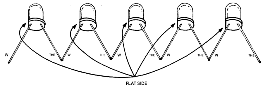
LEDs are undoubtedly the components that should be analyzed first. Practically any LED, of any type or color, can be used. It will always be convenient if the reader uses LEDs of different colors, at least their sizes should be the same. The recommended LEDs are the low-cost, general-purpose type, with the shape shown in Figure 7.
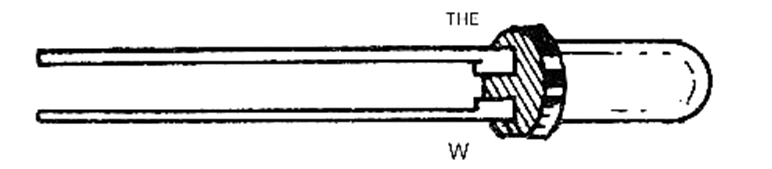
Note that these LEDs have a flat part on their casing, which is important because it determines how they are connected. The SCR can be a C106, MCR106, or IR106 for a voltage of 200V if your mains voltage is 110V and for 400V if your mains voltage is 220V. The transformer is the type used in vacuum tube circuits. Ask for an output transformer for the 6AQ5 or 50C5 tube and everything will be solved.
Note that the enameled wire winding is connected to the input circuit and the flexible plastic wire winding is connected to the SCR trigger circuit. If this transformer is unavailable, the reader can try using a power transformer for 6, 9, or 12V x 250mA (or slightly more) connecting the low-voltage winding to the input circuit. Resistors R1 and R3 are determined by the power of your amplifier, the voltage of your power supply, and the number of LEDs you intend to power.
The tables are given below:
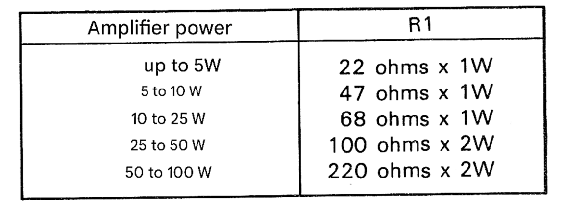
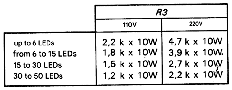
The 47k resistor (R2) is not critical, its value being constant for any power and voltage of the mains. Capacitor C1 can be of any type and its value will be in the range of 4.7k to 47k. The choice of value is determined by the type of sound the reader wants their LEDs to follow.
If you want a more intense bass response, you should use a larger capacitor, and if you want a more intense treble response, you should use a smaller capacitor.
Regarding the enclosure, since the components used are small, the reader can start with a plastic or wooden one of approximately 10 x 15 x 10 cm for mounting with the LEDs on the panel and the sensitivity control, a common 47k potentiometer to which the main switch will also be connected.
If the enclosure used is metal, the reader must take the utmost care to keep all connections isolated from it to avoid short-circuit problems. Next, we describe the general assembly, along with any potential problems that less experienced users might encounter.
ASSEMBLY
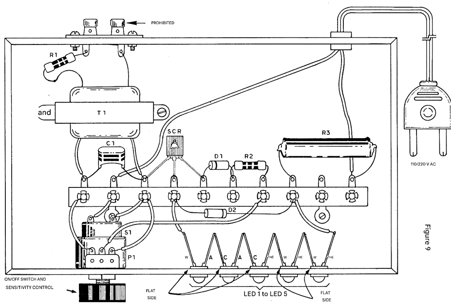
The few electronic components that require support by their own terminals can be soldered onto a terminal strip, thus eliminating the need to create a printed circuit board. This simplifies assembly, especially for beginners who do not have many technical resources in their workshop.
Larger components such as the transformer and potentiometer are then fixed to the case itself, while smaller ones are soldered directly onto a terminal strip. The LEDs will all be fixed to the panel according to the layout the reader imagines.
Soldering should be done with a low-power soldering iron (maximum 30 W), and as additional tools, the reader will need side-cutting pliers, needle-nose pliers, screwdrivers, and a wire stripper. Figure 8 shows the complete circuit of the RHYTHMIC LEDs, with the component values. R1 and R3 are determined from the table according to the power of your amplifier, the number of LEDs connected, and the voltage of your mains supply.
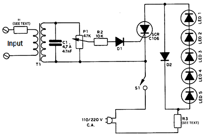
Figure 9 shows the component layout on the terminal strip and its placement in the enclosure.
After preparing the enclosure for assembly, drilling holes for the potentiometer, LEDs, audio and mains input wires, heat the soldering iron and connect the components as follows:
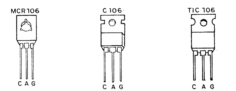
a) Start by soldering the SCR to the terminal strip, observing its position according to the diagram. See Figure 10 for terminal identification if your SCR is of a different type.
b) Next, solder the diode, D1, observing its polarity indicated by the ring on its body. This soldering should be done quickly to avoid heat damage.
c) No special care is needed to solder resistor R2, except to avoid excessive heat, which could damage it. The value of this component is indicated by its colored rings.
d) Next, solder resistor R3, which limits the current to the LEDs. Determine the correct value for this resistor based on the number of LEDs you intend to use. For the 5-LED version with a 110V power supply, use a 2.2kΩ resistor with 10W dissipation. Note that during soldering, the terminals of this component should not be cut too short, as some of the generated heat is dissipated by them. The component body should also be kept away from other components to prevent heat from affecting them. Solder capacitor C1 as well.
e) Finish soldering the components to the bridge with diode D2. Note its position, which is determined by the painted ring on its body.
f) With the components soldered to the bridge, attach the transformer, the input terminals, the potentiometer, and the LEDs. Then, connect all these components to the bridge using flexible plastic-coated wire. Use wires of sufficient length to allow for easy handling of the bridge without the risk of breakage. Also, note that resistor R1, whose value depends on the amplifier's power, is soldered directly between the input terminal block and the transformer.
g) For the transformer connection, it is very important that the reader observe the position of this component. The winding with thicker enameled wire goes to the sound input, while the winding with flexible plastic-coated terminal wires (primary) goes to the potentiometer and the capacitor.
Complete the assembly by soldering the power cable. Check the LED soldering to ensure they are all connected correctly. Figure 11 shows how these components can be connected.
Once the assembly is complete, check all connections. If everything is in order, you can perform the functional test and final installation.
TESTING AND INSTALLATION
Figure 12 shows how to connect the amplifier output to the input of the rhythmic LED set.
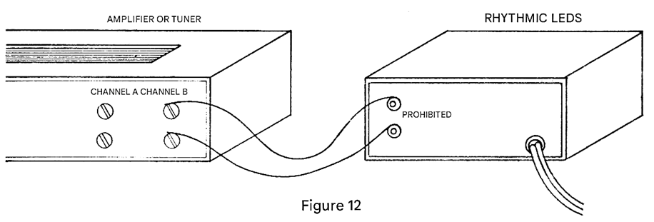
Note that it is not necessary to observe the color of the output terminals. Even if reversed, the device will function normally. With the connection made, activate P1 and set your amplifier to play at half volume. Then adjust P1 so that the LEDs blink in the same rhythm as the music.
If the LEDs do not light up, check if any of them are reversed or burned out. For this purpose, with a piece of wire, short-circuit 1, 2, and then 3 LEDs in sequence, as suggested in Figure 13.
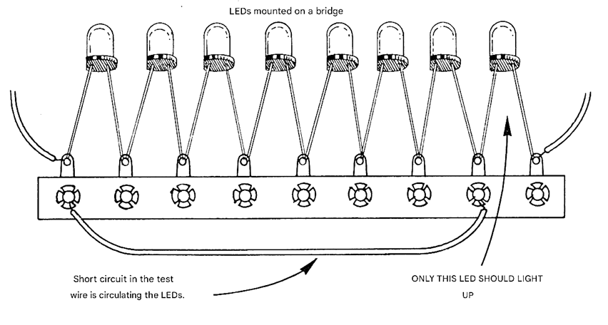
If removing one LED from the circuit causes the others to light up, it means that the LED is burned out. If in doubt, place one LED in the circuit first, and then turn on the others. If the LEDs remain constantly lit, check the SCR's condition. Try connecting a 1kΩ x 1/8W resistor between its cathode (C) and gate (G).
To use it, you will see that you will need to adjust the potentiometer depending on the music level. If you want to change the frequency response of your rhythmic LED array, simply change the value of capacitor C1 as desired.
Once the device is working normally, install it permanently near the sound system, enclosing its enclosure. When not in use, it is not necessary to unplug it, as there is no power consumption with the LEDs off.
LIST OF MATERIALS
SCR - C106, MCR106 or IR106 - silicon controlled rectifier
D1, D2 - 1N4004 or equivalent - silicon diode
T1 - output transformer (see text)
P1 - 47 kΩ potentiometer with switch
R1 - see text
R2 – 10 kΩ x 1/8 W - resistor (brown, black, orange)
R3 - see text
C1 - 4.7 to 47 nF - metallized polyester capacitor
LED1, LED2, etc. - common red, yellow or green LEDs.
Miscellaneous: enclosure for assembly, terminal block, wires, solder, LED holders (optional), input terminals, power cable, etc.


