
ART1959S ART2278
By stepped timer, we understand a type of timer capable of indicating the various timing stages and even performing intermediate activation of devices. Although in our original project we worked with 3 indication steps and one activation step, nothing prevents the circuit from being modified for more indication or activation steps. The circuit is powered by a 6V supply, but by simply changing the relay and a few resistors, we can change it to 12V. The circuit is based on the quad voltage comparator from the 139 series, which can be the CA139, CA239, CA339, or the LM139, LM239, or LM339, all easily obtainable and quite affordable.
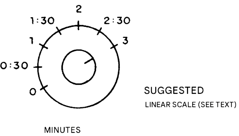
We provide two timing ranges in the circuit, selected by simply changing capacitors, leading to intervals of a few seconds up to 2 or 3 minutes in the smaller range and up to several tens of minutes in the larger range. Using a common clock or stopwatch, we can create a graduated scale for the time adjustment potentiometer. This is suggested in Figure 1.
Four voltage comparators are connected in such a way as to have stepped references, as shown in Figure 2.
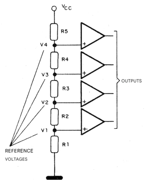
Simple indicator LEDs are connected to the first three, and a transistor that drives a relay is connected to the last one. When an RC timing circuit is connected to the comparator inputs, as the voltage rises, each comparator is activated, causing the corresponding LED to light up.
When a sufficiently high voltage is reached for the last comparator to be activated, the relay is activated, allowing it to control an external load. In the original circuit, the comparators have their reference fixed in steps, determined by 1k resistors, and there is an adjustment trimpot (10k) to set the ideal activation point. For timing, we use 47 and 470 uF capacitors with a 1M potentiometer. We cannot use larger resistors, given the input impedance of the comparators.
Note that by connecting the reference to the non-inverting inputs and making the timing circuit input through the inverting inputs, we have the comparators switching from high to low level when the LEDs light up and the relay is activated. In Figure 3 we provide a modification that allows for a different operation of the circuit.
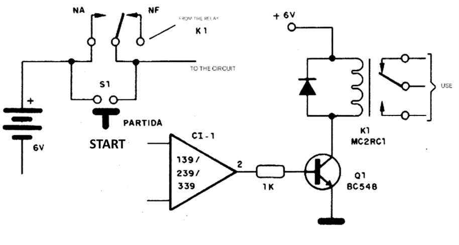
In this configuration, we press S1 to activate the relay, which, during the interval set in P1, keeps the timer and the external load activated. At the end of the interval, the relay trips and simultaneously disconnects the timer's power supply. This is an ideal version to be used as a TV timer. Some considerations regarding linearity become interesting. If we take the charging graph of a capacitor in a series RC circuit, we will have the curve shown in Figure 4.
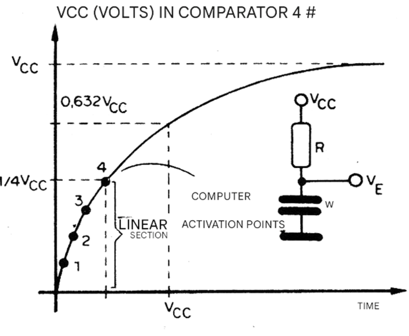
As we can see, in the initial charging section, when the capacitor is practically discharged and the voltage on the plates is small compared to the supply voltage, the current remains constant, resulting in a linear section of the characteristic. If we adjust the timer so that the comparator firings are located in this section, we will have a practically linear scale for the P1 time adjustments.
On the other hand, if the firing points are spread over a larger section, the presence of a curve in the characteristics already alters this linearity.
To achieve good linearity, the comparators must be adjusted, via P2, so that they have a maximum trigger voltage of 1/4 of the supply voltage; that is, we must adjust each comparator to trigger approximately 0.4 V above the previous one, as shown in Figure 5.
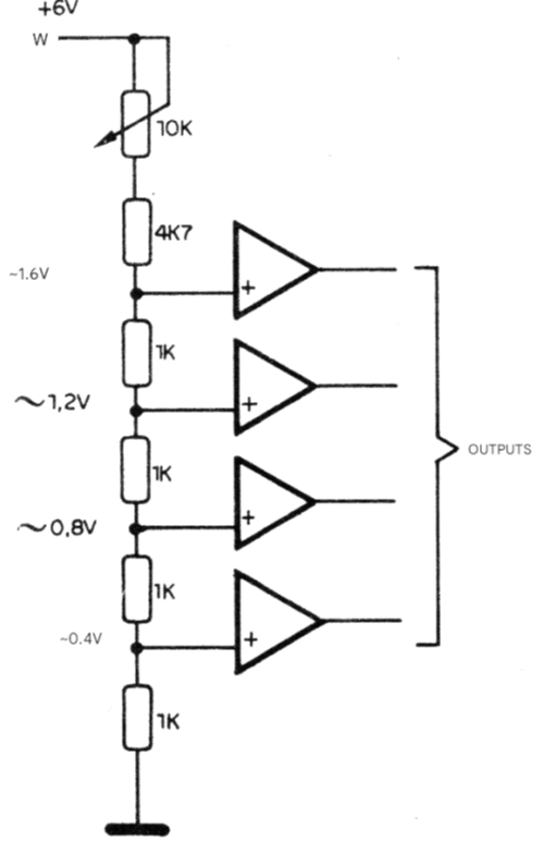
For this, considering the use of 1 kΩ resistors, which results in 4 kΩ for the divider, the last resistor should be approximately 3 times larger, that is, around 12 kΩ. For this reason, the adjustment consists of a 10kΩ trimpot in series with a 5k6 or 6k8Ω resistor.
This linearity of the circuit characteristics has the advantage of a precise scale adjustment; however, it limits the maximum time interval we can obtain. Thus, even using capacitors with high values, we cannot achieve large intervals because the value of P1 is limited by the input resistance of the comparators and the existence of leakage in the capacitors themselves.
ASSEMBLY
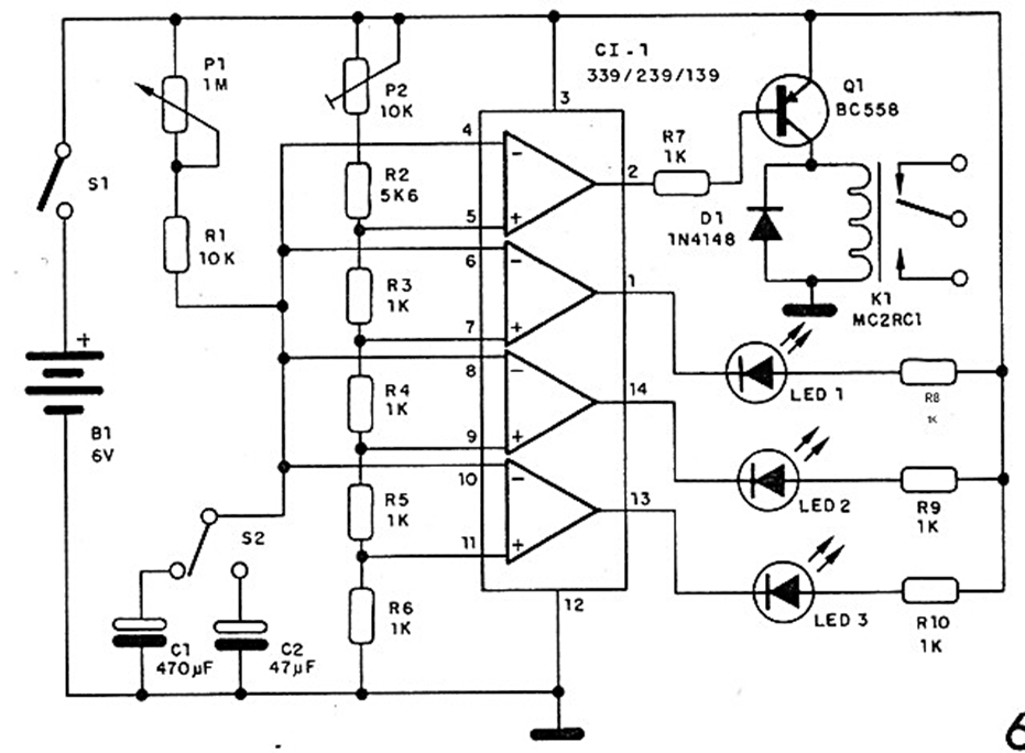
Figure 6 shows the complete diagram of the timer in its basic version, for energizing the relay at the end of the programmed interval.
The printed circuit board assembly is shown in Figure 7, the design being based on the original components given in the bill of materials.
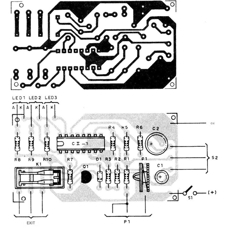
If components of different dimensions are used, a redistribution on the board must be made, with the necessary layout changes. LEDs are standard and the relay is a miniature type for 6V, if this is the chosen power supply. For a 12V power supply, replace the relay and resistors R8 to R10 with 1.2kΩ or 1.5kΩ resistors. Q1 is a BC558, or any equivalent general-purpose PNP transistor, and the resistors are all 1/8 or ¼ W with 5 or 10% tolerance.
The electrolytic capacitors must be of good quality and have a working voltage of at least 6V for this power supply version. For P1 we use a linear potentiometer, which can also be combined with switch S1. P2 is a trimpot. For the power supply, we can use either 4 standard batteries (small or medium) or a power supply, which must have good regulation. A power supply with a 7506 IC is the most suitable. The external load can be connected via a wall oulet or a screw terminal block.
TESTING AND USE
Adjust P1 to the desired time; set S2 to the position that selects the smallest capacitor (initially) and turn on S1. The LEDs should light up sequentially until the relay is activated. Once operation is verified, adjust P2 so that the voltage at the junction of R2 and R3 is approximately 1.5 V. This will cause the circuit to operate in the linear region of the capacitor's charging curve. If this linearity is not important and you wish to extend the maximum time obtained, replace P2 with a 2.2kΩ trimpot and resistor R2 with a 2.2kΩ resistor, adjusting the trimpot to obtain a voltage between R2 and R3 of 3 to 4 V.
If, after the third LED lights up, the relay takes a long time to energize or if it does not, check the condition of the timing capacitors, which may have leakage. Once operation is verified, simply connect the load to the output and adjust the desired time. Activate S1 to turn it on, or perform the shutdown version, as indicated in the operation section. The maximum load should not exceed 2 A (200 W on a 110 V network).
LIST OF MATERIALS
IC-1 - LM139, LM239, LM339 or CA139, CA239 or CA339 - voltage comparators
Q1 - BC558 - general-purpose PNP transistor
LED1 to LED3 - common LEDs
D1 - 1N4148 - general-purpose silicon diode
Kl - 6V micro-relay
S1 - simple switch
S2 - 1-pole x 2-position switch (optional)
B1 – 6V - 4 small or medium batteries
P1 – 1MΩ - linear potentiometer
P2 – 10kΩ - trimpot
R1 – 10kΩ - resistor (brown, black, orange)
R2 - 5kΩ - resistor (green, blue, red)
R3 to R10 – 1kΩ x 1/8W – resistors (brown, black, red)
C1 – 470uF - capacitor electrolytic
C2 – 47 uF - electrolytic capacitor
Miscellaneous: printed circuit board, mounting box, battery holder, output bridge or socket, socket for the integrated circuit, knob and scale for the potentiometer, wires, etc.


