
ART015S ART2288
In the protection of power supply networks, circuit breakers are used, usually thermally operated, which trip, interrupting the current flow in case of a short circuit. The circuit breaker we present is electronic, for direct current sources up to 1 A. This circuit trips when the current rises above a certain pre-set value on a trimpot, causing the main transistor to cut off, thus interrupting the flow of this current.
As the circuit is a voltage sensor, as long as the short circuit is maintained, there is no reset. The assembly of this system is quite simple, and the few components used allow it to be integrated into common power supplies. Modifications to the original circuit can be made to increase its current capacity.
THE CIRCUIT
The two diodes (D1 and D2) stabilize the base voltage of transistor Q2. In this way, we have a constant current source that biases the base of Q1. The collector current of Q1 will then be given by the constant collector current of Q2 multiplied by its gain. This value gives us the maximum intensity of control of the circuit. Transistor Q1 operates in the ascending part of the IC/Vce characteristic curve, where there is an elbow where saturation begins (Figure 1).
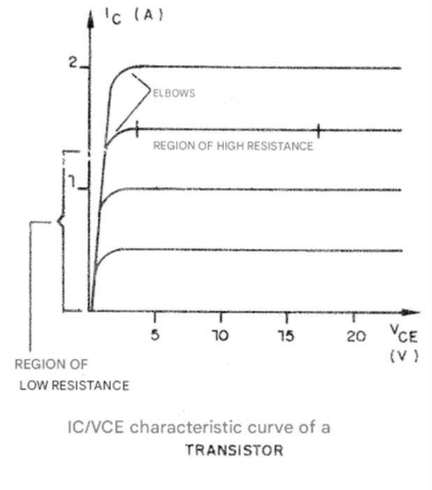
From the elbow, the curve becomes practically horizontal. We then have two sectors, one ascending section of the curve and another practically horizontal, which differ in the internal resistance presented by the transistor. In one case, we have a very high resistance and in the other a very low resistance.
The transistor normally operates in the low resistance sector, allowing all possible current to pass to the load. However, if a short circuit occurs at the output, the operating point shifts to the section with high resistance. Under these conditions, transistor Q2 can no longer maintain a constant collector current, thus disabling the load.
Note that transistor Q1 must be equipped with a good heat sink, as it tends to overheat in the event of a short circuit.
ASSEMBLY
Figure 2 shows the complete diagram of the device.
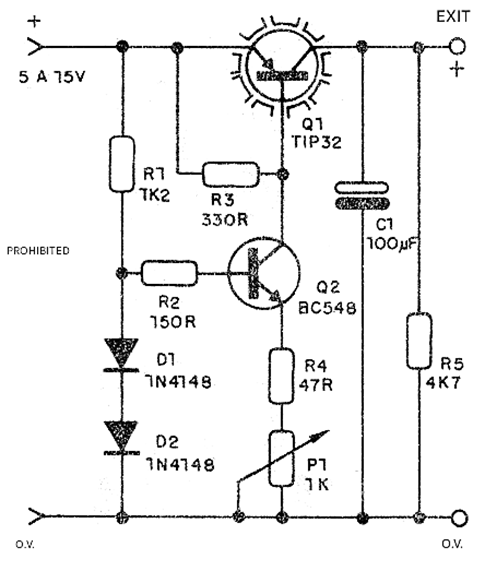
Figure 3 shows a small, printed-circuit board for this assembly.
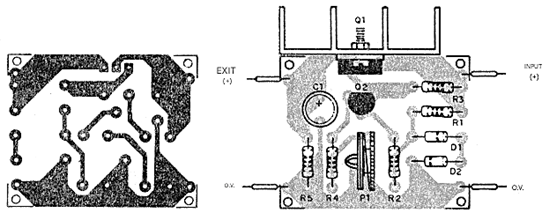
The resistors are all 1/8 or ¼ W and the electrolytic capacitor should have a working voltage slightly higher than the output voltage of the power supply. Equivalents to the indicated transistors can be used.
For Q2 we have BC237, BC238, BC547 etc. For Q1 we can use other power PNP transistors such as the TIP42 and the BD138, the latter for a maximum current of 1 A.
Adjustment and Use
The only adjustment is the trip point, made at P1. Connect the circuit breaker to the output of a power supply and a voltmeter to the output of the circuit breaker. There should be an indication of the desired output voltage. Next, apply the maximum load expected to cause the shutdown to the output and adjust P1 so that the voltage drops to zero.
Without a load or with smaller loads, the voltage should be normal, and with the maximum load or slightly less, the system should activate. Once the operation is verified, simply install the device permanently on a power source.
LIST OF MATERIALS
Q1 - TIP32 or equivalent - PNP power transistor
Q2 - BC548 or equivalent - general-purpose NPN transistor
D1, D2 - 1N4148 - general purpose silicon diodes
P1 – 1 kΩ - trimpot
C1 – 100 uF - electrolytic capacitor
R1 - 1.2 kΩ - resistor (brown, red, red)
R2 - 1500 Ω - resistor (brown, green, brown)
R3 - 3300 Ω - resistor (orange, orange, brown)
R4 - 470 Ω - resistor (yellow, violet, black)
R5 - 4.7 kΩ - resistor (yellow, violet, red)
Miscellaneous: printed circuit board, heatsink for Q1, wires, solder, etc.


