
The purpose of the circuit of figure 1 is to power a load with an up to 2A constant current from 12 V supply.
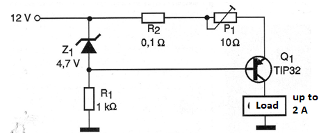
The loads can be heating elements, motors, solenoids and other devices that need a constant current for their operation. The current strength is set in the 10 ohm wire potentiometer. The zener diode can be of voltages close to 4.7 V with 400 mW at 2 W dissipation.
The resistor R2 should preferably be wire can be improvised with the connection of 5 resistors of 0.47 ohms x 0.5 W in parallel. The transistor Q1 accepts equivalents of equal or greater current capacity and must be mounted on a good heat radiator.
In figure 2 we have a suggestion of printed circuit board for the assembly.
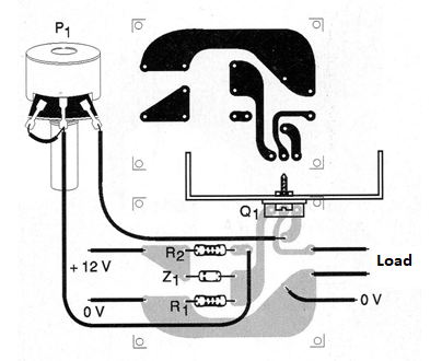
Note that the higher current tracks should be wider.
Material list
Q1 - TIP32 or equivalent - Power PNP transistor
Z1 - Zener diode of 4.7 V x 400 mW or equivalent - BZX79C4V7 or equivalent
R1 - 1k ohm x 1/8 W - resistor - brown, black, red
R2 - 0.1 ohm x 1 W or larger - wire resistor
P1 - 10 ohm - wire potentiometer
More:
Printed circuit board, heat radiator for transistor, wires, solder, etc.


