
This type of oscillator uses an unusual setting and can be used as a time base, metronome or rhythm. Metronomes or rhythms are devices that produce light or sound signals at regular intervals in order to set the tempo of a gymnastic exercise, repetitive physical activity, or even the performance of a song on any instrument. The circuit we propose can be used for the suggested purposes and many others, such as for example in signaling.
The rhythm of the music performed by an apprentice is not always constant, which requires the use of devices called metronomes. The simplest type is the pendulum that besides the noise (tic-tac) has the balance to serve as the base so that the musician does not leave the rhythm.
This same type of metronome can be found in experimental physics labs for experiments involving constant time intervals. The circuit we propose produces only sound, and with good volume, serving for music students, for the physics lab as well as for gymnastics.
In this device we have a different relaxation oscillator, based on a neon lamp and an SCR, which produce good intensity pulses on a loudspeaker. The frequency range goes from fraction of hertz to some hertz. The device is powered directly by the 110V or 220V power network and has excellent performance taking into account the small number of components used.
The reader has the following possibilities of use for this device:
• Music Tracking
• Fixing rhythms for gymnastic or dance exercises
• Time limitation by pulse counting
• Physics Experiences
Features:
• Power supply voltage: 110/220 VAC
• Consumption: 1 W (approx.)
• Pulse power: 4W (peak)
• Frequency range: 0.05 to 10 Hz
HOW IT WORKS
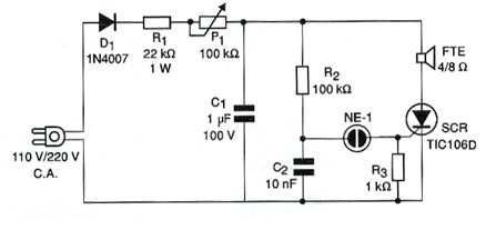
The voltage of the power grid is rectified, serving to slowly charge, through R1 and P1, the capacitor C1. The charge of this capacitor determines the energy or power of the sonic pulse to be produced. When the voltage in the capacitor reaches approximately 80V, which is the voltage of the neon lamp, at the same time through R2 reaches the same value the voltage in the capacitor C2. This occurs because the time constant of R2 and C2 is much smaller than that of the circuit formed by P1, R1 and C1.
With this voltage, the neon lamp fires and thus the conduction of a current to the SCR gate. The end result is that, by conducting the SCR, the capacitor C1 is practically shorted through the loudspeaker. The consequent discharge is a single pulse of short duration and great intensity that produces a sound in the loudspeaker.
Upon discharge of the capacitor, the SCR will shut down and again the capacitor C1 will discharge until the trip voltage of the neon lamp and therefore of the SCR is reached again. The frequency is basically given by the rate at which C1 is loaded and therefore can be set at P1. Larger capacitors for C1 produce more intense pulses, but there is a limit to this value because too high current in the discharge can damage both the SCR and the speaker.
Capacitors up to about 20 uF with150 V working voltages can be tried.
ASSEMBLY
In figure 1 we have the complete diagram of the metronome.
Since few components are used, a small printed circuit board can be used for assembly. Thus, we have the arrangement of the components in this board shown in figure 2.
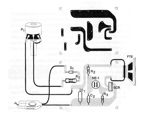
The resistor R1 must be 1W and the others must be 1/8W or larger. O capacitor C1 can be both polyester and electrolytic from 1 to 10 uF with minimum working voltage of 150V. The capacitor C2 must be polyester with at least 150V working voltage. For the 110V network the TIC106B can be used and for the 220V network the SCR TIC106D is recommended. The neon lamp and the potentiometer are of common types.
For the diode D1 we have the 1N4004 or 1N4007 if the network is 110V, but if it is 220V only 1N4007 should be used. The loudspeaker, 4 or 8 ohms at least 10 cm in diameter.
TEST AND USE
An important point to note in this project is that its power supply is made directly by the power grid and that is why its circuit is subjected to high voltages capable of causing dangerous shocks. Therefore, when testing the player, all precautions must be taken in relation to this and in the assembly, it must isolate or close in the box any parts that may cause a contact shock.
Turning the unit on the mains and adjusting P1 we should have blinks of the neon lamp and at the same time the emitting rhythms of the loudspeaker. If the lamp blinks but there is no sound, check the speaker coil continuity and SCR status. If the blinks are too fast and there is no sound, the problem may be in C1.
Once the operation is proven, the assembler can add a scale to the P1 knob which can be calibrated in terms of beats per minute or even in hertz. After that, just close the device permanently in a plastic or wooden box and use it. The neon lamp may be visible in order to obtain a visual rhythm.
For lower frequencies increase P1 to 1 M ohms and C1 to 2.2 or even 4.7 uF.
MATERIAL LIST
Semiconductors:
SCR - TIC106B (110V) or TIC106D (220V) - silicon controlled diode
D1 - 1N4004 or 1N4007 - diode - see text
Resistors:
R1 - 22k x 1W - Red, Red, Orange
R2 - 100k ohm x 1 / 8W - brown, black, yellow
R3 - 10 k ohm x 1 / 8W - brown, black, orange
P1 - 100k ohm - potentiometer
Capacitors:
C1 - 1 uF x 150V - polyester or electrolytic
C2-10 nF (103 or 0.01) - polyester capacitor
More:
NE-1 - common neon lamp
FTE - 4 or 8 ohm x 10 cm - common speaker
Printed circuit board, power cable, mounting box, potentiometer knob, wires, solder, etc.


