
This simple battery-powered circuit flashes a neon lamp at speeds ranging from a few flashes per second to a flash every 5 seconds or so, depending on the values of the components used. Simple to assemble, the device can have some interesting uses.
One way to determine the speed of rotation of a motor is by a device called strobe. When illuminating with a pulsating light a moving propeller or a wheel bearing a mark, an important phenomenon occurs. The movement of the wheel or propeller is visually paralyzed when rotation becomes multiple of the frequency of the blinks.
If we calibrate the circuit that produces the blinks in terms of frequency or rotations we can measure the rotation of the object.
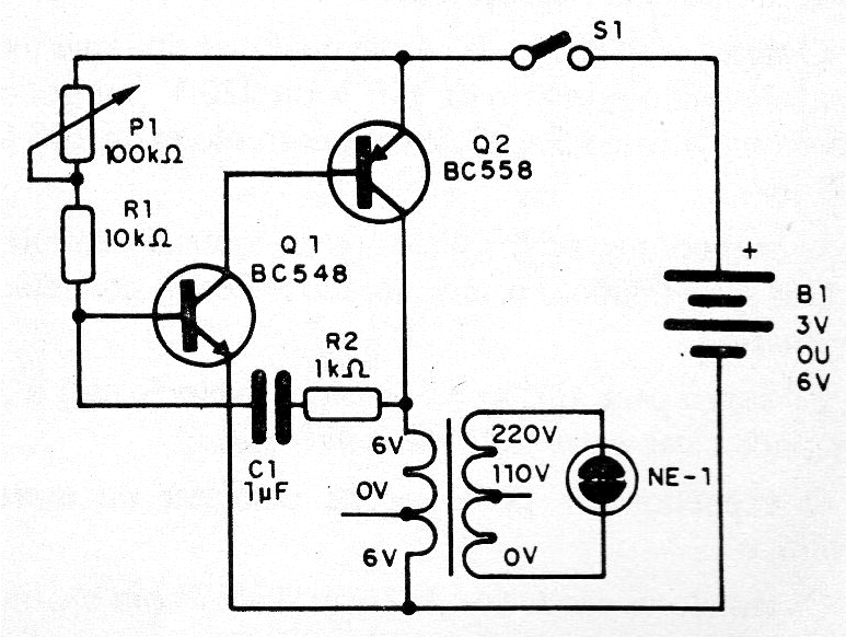
The apparatus described is a very simple stroboscope, but it can be calibrated and optimized for use on the bench or other important applications. The advantage of this circuit is that the neon lamp can flash at a much higher speed than a standard lamp, which does not apply to this project. In the figure we have the complete diagram of the strobe with neon lamp.
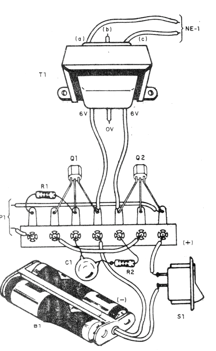
In figure 2 we have its assembly based on a terminal strip. The transformer is a 5 to 9 V secondary power supply type with 50 to 250 mA current.
The neon lamp is common NE-2H but small fluorescent lamps of 2 to 5 W will also flash when used in this circuit. More power can be obtained by exchanging Q2 for a BD136 with a heatsink and supplying the circuit with a voltage of 12 V. You can change the frequency range by changing C1 which can assume values between 47 nF and 2.2 nF on this circuit.
Material list
Q1 - BC548 - General Purpose NPN Transistor
Q2 - BC558 - General Purpose PNP Transistor
NE-1 - Common neon lamp - see text
T1 - Transformer - see text
P1 - 100 k ohm - trimpot or potentiometer
R1 - 10k ohm x 1/8 W - resistor - brown, black, orange
R2 - 1k ohm x 1/8 W - resistor - brown, black, red
C1- 1 uF - polyester capacitor
B1 - 3 to 6 V - cells - see text
S1 - Single Switch
Miscellaneous: terminal strip, battery holder, wire, solder, etc.


