
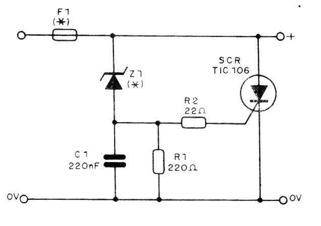
This overvoltage protection circuit works in an interesting way: when the output voltage exceeds the value set by zener Z1, the SCR triggers and shorts the output, causing the fuse to blow. In this way the circuit power is immediately cut off.
The zener is then determined by the voltage at which the current is to be cut and the fuse must have an intermediate value between the maximum current required by the supplied load and the maximum current the source can supply (shorted current).
In figure 1 we have the complete diagram of this system and in figure 2 its assembly based on a small terminal bridge.
The resistor R2 will have 22 ohm for voltages from 5 to 9 V. For voltages from 9 to 15 ohm, use 220 ohm and for voltages above 15 V use 1k.
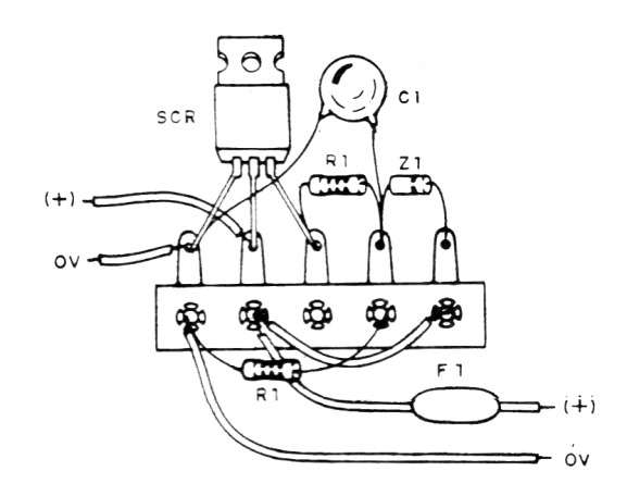
The zener is ½ W or more for voltages in the range of 5 to 30 V. The circuit is interspersed between the load and the power supply.
Material list
SCR - TIC106 - Silicon Controlled Diode
Z1- ½ W or more zener diode - see text
F1- Fuse - see text
C1 - 220 nF - Polyester or Ceramic Capacitor
R1 - 220 ohm x 1/8 W - resistor - red, red, brown
R2 - 22 ohm x 1/8 W - resistor - red, red, black
Miscellaneous: terminal strip, fuse holder, wires, solder, etc.


