
It is an "economical" circuit which replaces the reed-switches with thin wires that are interrupted when the door or window is opened.
The only drawback of this version is that every night the wires should be placed in working position.
These wires are attached to two nails, one in the fixed part and the other in the moving part of the window and connected to the main circuit by means of a pair of camouflaged wires.
In Figure 1 we have the complete circuit of this system.
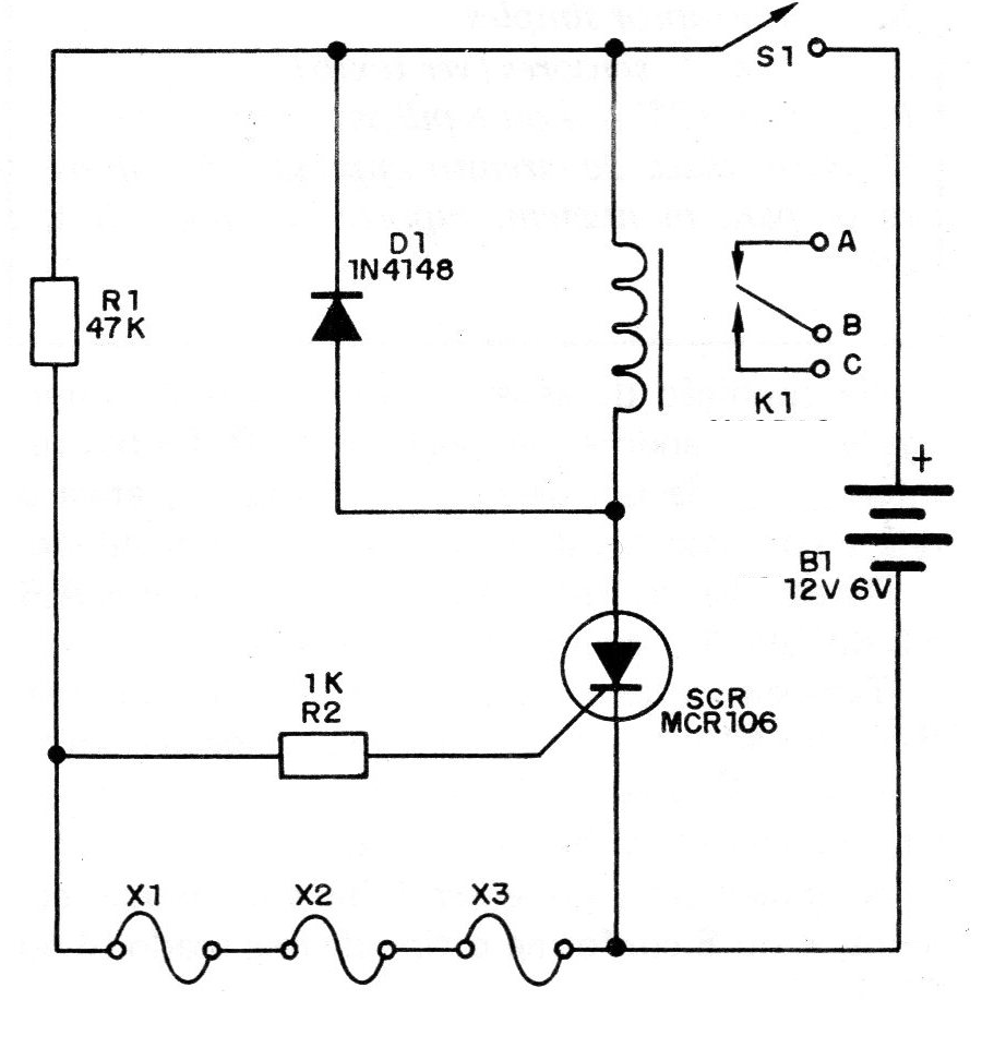
In standby condition all wires are interconnected, grounding the SCR gate. If one of them is interrupted, the SCR triggers, activates the relay and the alarm system is powered.
The connections of the warning system to points AB and C of the relay are done in the conventional manner.
Also in this case, once activated, to reactivate, it is not enough to redo only interrupted connections. You need to turn S1 off and on again, which should be well hidden.
The power can be supplied with standard batteries, 4 or 8 depending on the type of the relay used (6 or 12V).
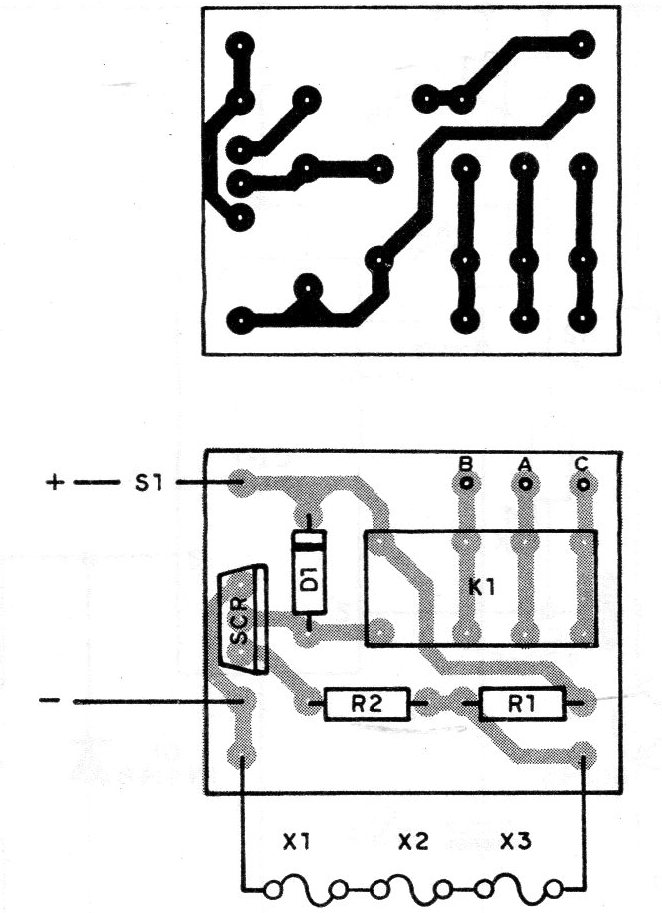
In Figure 2, we give the printed circuit board.
MATERIAL LIST
SCR - MCR106, TIC106 or C106 - Common SCR
K1 - Sensitive relay for 6 or 12 V
D1 - 1N4148 or 1N914 - general purpose diode
R1 - 47 k x 1/8 W - resistor (yellow, violet, orange)
R2 - 1k x 18W - resistor (brown, black, red)
S1 - single switch
X1, X2, X3 - sensors (see text)
B1 - 6 or 12 V - 4 or 8 batteries
Miscellaneous:
Printed circuit board, thin wires, mounting box, battery holder, wires, etc.


