
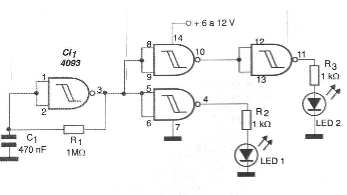
This circuit may be of interest for generating warning signals on machine panels or other places where a flashing light alternately changing from green to red is required. The oscillator shown in figure 1 can drive both two separate LEDs and a two-color LED on a frequency that depends on both R1 and R2.
These components can be changed over a wide range of values. The resistors R2 and R3 can also be changed as a function of the supply voltage in order to obtain greater or less brightness for the LEDs. Values between 330 ohm and 1 k ohm are recommended. The same circuit can excite higher power steps to activate lamps, even connected to the power grid if SCRs are used.
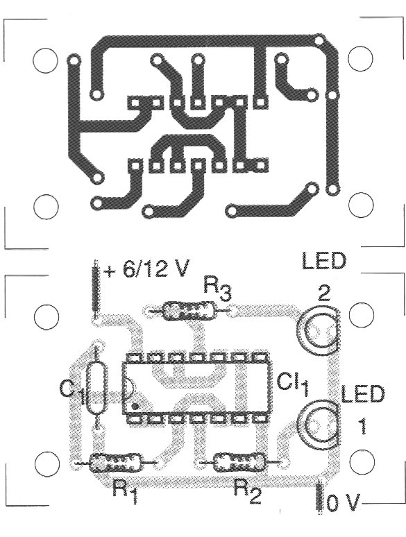
In figure 2 we have a suggestion of printed circuit board for implementation of this luminous warning system.
MATERIAL LIST
CI-1 - 4093 - CMOS integrated circuit
LED1, LED2 - red and green or bi-color LEDs
R1 - 1 M ohm x 1/8 W - resistor
R2, R3 - 1 k ohm x 1/8 W - resistors
C1 - 470 nF - ceramic or polyester capacitor
Several:
Wires, solder, printed circuit board, etc.


