
A higher power solution using discrete components and that has been used extensively in commercial equipment for decades past is based on the complementary pair BD135 / BD136. Providing excellent sound quality it has been adopted in many commercial amplifiers for its ease of implementation and fidelity.
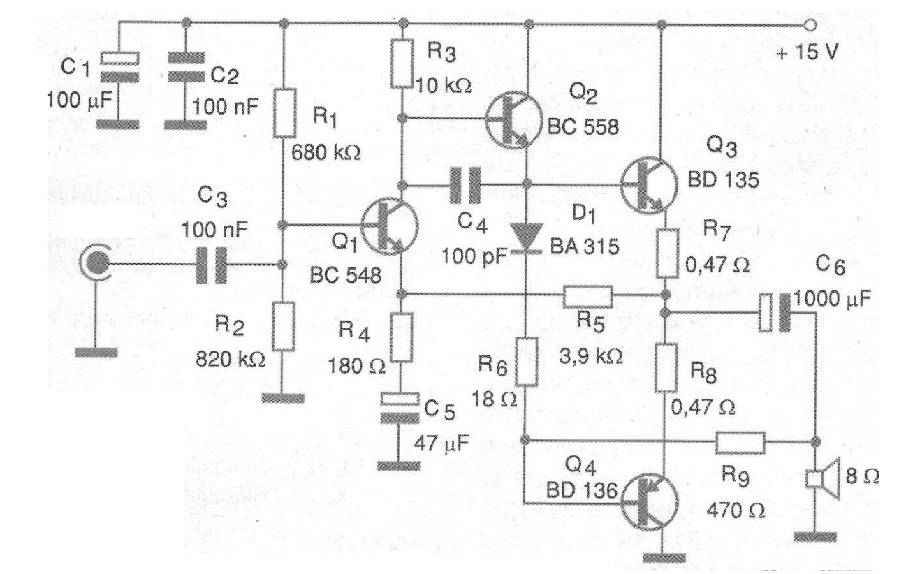
If the reader needs a medium power step for an application and wants a rather traditional, even didactic, analogue solution, the one we present in figure 1 deserves to be analyzed.
The printed circuit board for mounting this amplifier is shown in figure 2.
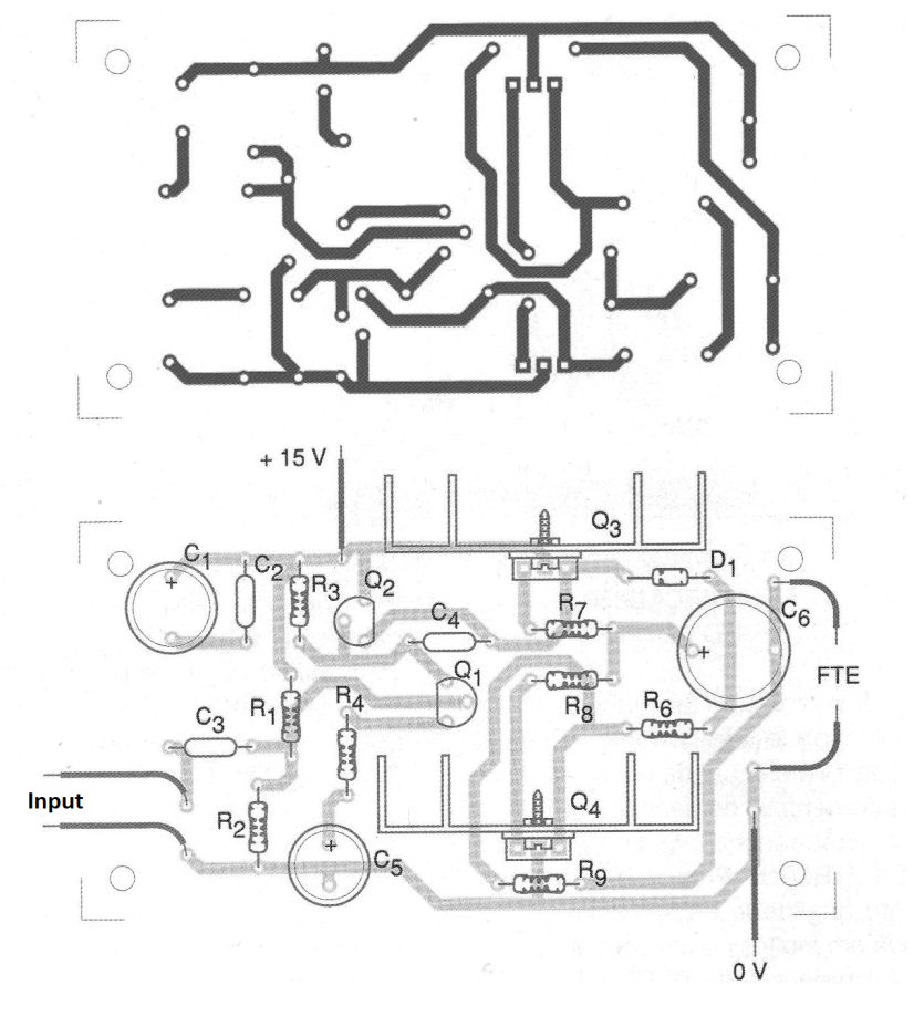
The power can be made with voltages from 12 to 15 V and the drain current will be around 800 mA. The output transistors must be mounted on heatsinks and an equivalent complementary pair is formed by the transistors TIP28 and TIP29.
Note, however, that the pinout of these transistors is not the same as the BDs.
The R5 resistor may eventually require minor changes to set the resting current, gain, and improve signal symmetry. The speaker should be 8 ohms at least 10 cm in diameter for best sound quality.
MATERIAL LIST
Semiconductors:
Q1 - BC548 or equivalent - NPN general purpose transistor
Q2 - BC558 or equivalent - general purpose PNP transistor
Q3 - BD135 - medium power NPN transistor
Q4 - BD136 - medium power PNP transistor
D1 - BA315 or 1N4148 - silicon diode
Resistors: (1/8 W, 5%)
R1 - 680 k ohm
R2 - 820 k ohm
R3 - 10k ohm
R4 - 180 ohm
R5 - 3.9k ohm
R6 - 18 ohm
R7, R8 - 0.47 ohm x 1 W
R9 - 470 ohm
Capacitors:
C1 - 100 uF x 16 V - electrolytic
C2, C3-100 nF - ceramic or polyester
C4 - 100 pF - ceramic
C5 - 1000 uF x 16 V - electrolytic
Several:
FTE - 8 ohm x 10cm or larger - speaker
Printed circuit board, power supply, wires, solder, etc.


