
This is an excellent sound reinforcement circuit for walkmans, small recorders, CD players and radios that have only headphone output. We can use the headphones output to get playback on a speaker at least 15 cm. Installed in a small speaker, the speaker with the booster and eventually its power supply will provide a much better sound for your portable equipment that has 2 or 4 standard batteries or just a headphone output.
The power supply must provide a voltage of 6 to 9 V with at least 500 mA. The circuit has only one transistor as a base and a single adjustment for better sound without distortion. In figure 1 we have the complete diagram of the booster.
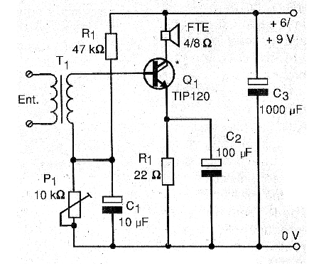
If your equipment is stereo and you want to strengthen the two channels you must mount two equal units that will be powered by a single power supply. In figure 2 we have the arrangement of the components in a small bridge of isolated terminals, since it is a circuit that is not very critical.
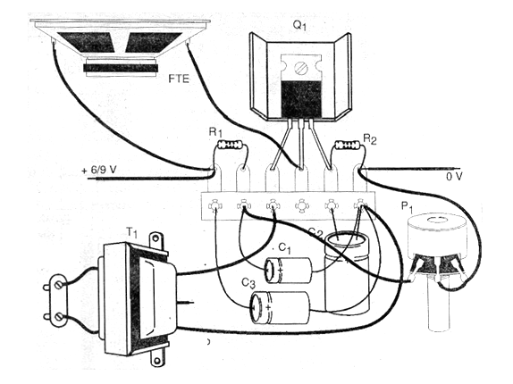
Transistor Q2 is a Darlington of power admitting equivalents. Actually any Darlington NPN with at least 4 amps of collector current can be used. This transistor should be provided with a small heat radiator. The resistors are all 1 / 8W or larger and the electrolytic capacitors must have a working voltage of at least 12 V.
The transformer may be of the type used as out-of-use transistor radios (the winding going to the speaker becomes the input winding), or a small 110/220 primary power supply transformer V and secondary from 5 to 12 volt with current between 50 and 250 mA. The low voltage winding is the one used at the input of the signals.
For best sound quality the speaker must be weighed at least 15 cm in diameter, installed in a small speaker according to its dimensions. After assembly, connect the unit to the power supply and set P1 to the middle position. Connect the input source to the signal source, which can be a radio or Walkman.
The signal is removed from the handset output (mono or stereo) with an appropriate plug. Adjust the volume until you get the maximum signal on the speaker and at the same time on P1 so that the sound comes out clean, without distortion. Once you have adjusted P1 for best playback you will no longer need to play this component. To regulate the sound intensity, act on the volume control of the signal source.
MATERIAL LIST
Semiconductors:
Q1 - TIP120 - Power Darlington NPN Transistor
Resistors: (1/8 W, 5%)
R1 - 47 k ohm - yellow, violet, orange
R2 - 22 ohm - red, red, black
P1 - 10 k ohm - trimpot or potentiometer
Capacitors:
C1 - 10 uF / 12 V - electrolytic
C2 - 100 uF / 12 V - electrolytic
C3 - 1000 uF / 12 V - electrolytic
Several:
T1 - transformer - see text
FTE - 4 or 8 ohm x 15 cm or larger - speaker
Terminal bridge, speaker, heat radiator for transistor, power supply, wires, solder, cable with plug for signal input.


