
In figure 1 we have a simple timer that uses only one super-transistor BC517 and which activates a relay for a time interval that depends on both the value of C1 and R1.
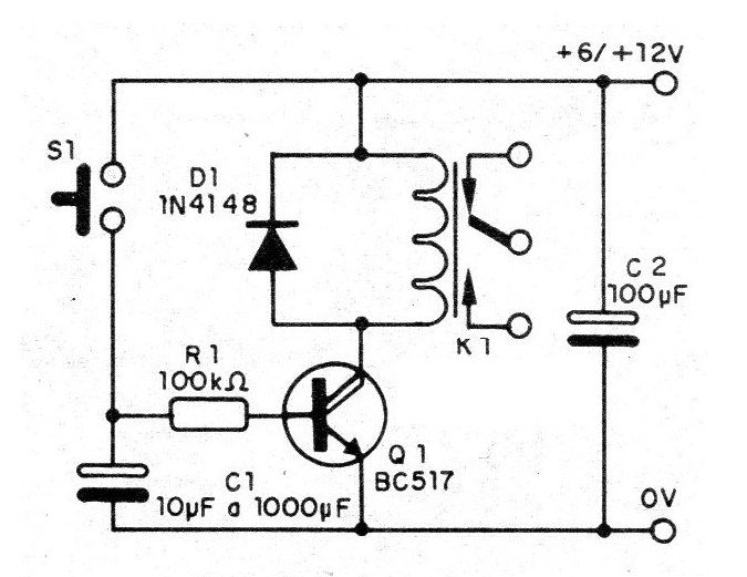
The reader may further increase the value of R1 for higher trigger ranges, but this component will be limited to values between 470 k ohm and 1 M ohm, the exact value being determined experimentally. By pressing S1 the relay will close your contacts and thus remain for a certain time.
This time is precisely given by the discharge of C1 through R1 and also of the super-transistor used. The layout of the components of this design on a printed circuit board is shown in figure 2.
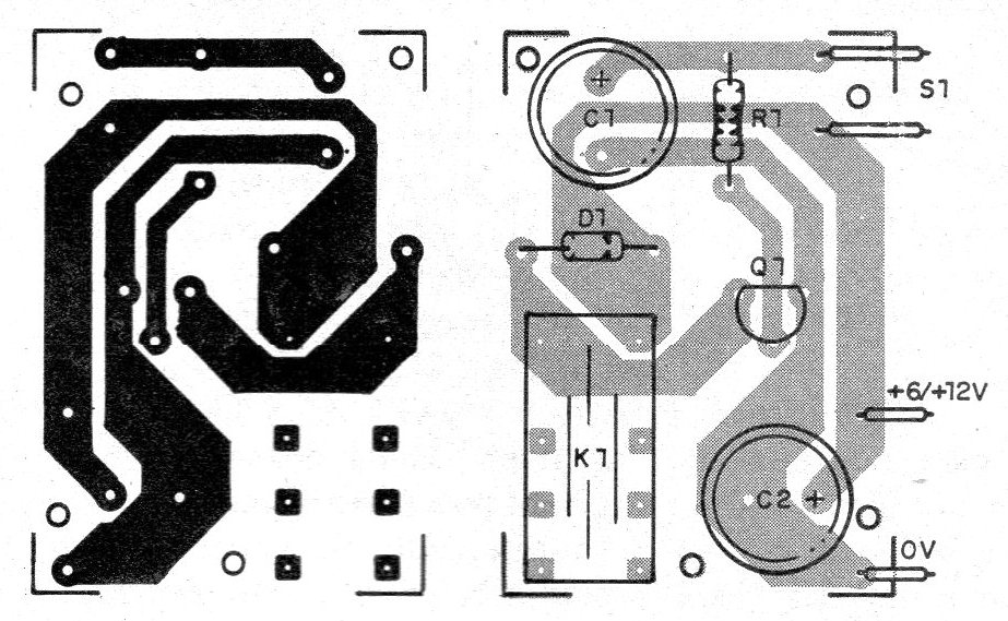
Depending on the supply voltage we can use 6 or 12 V relays. The types indicated have contacts that control currents up to 2 A.
Material list
Q1 - BC517 - Darlington transistor
D1 - 1N4148 - general purpose diode
S1 – Push Button NA
K1 - 6 or 12 V relay
R1 - 100 k ohm - resistor - brown, black, yellow
C1 - 10 uF to 1 000 uF - electrolytic capacitor
C2 - 100 uF - electrolytic capacitor
Several:
Printed circuit board, wires, solder, etc.


