
An unquestionable utility tool on the repair bench or even the assembler is the signal follower. With it, we can follow the signals in the various stages of electronic devices, such as radios, amplifiers, televisions, etc., so as to arrive at the one that has poor functioning. Once the problem step is separated, it is much easier to locate the component responsible: simply use the multimeter initially by measuring voltages and then testing the components themselves.
The follower we describe is ideal for the beginner because of its simplicity. However, it is sensitive enough to locate problems on most devices. Powered by ordinary batteries, it easily fits into a plastic box that is slightly larger than a soap dish.
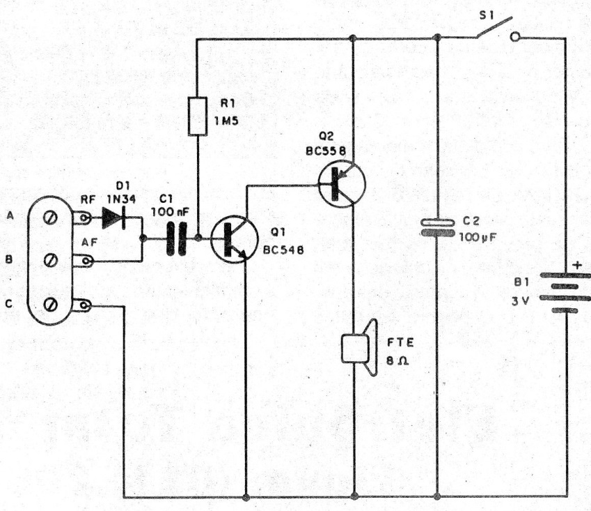
In fact, the component that determines the size of the box is the speaker. The circuit has two inputs, one for audio signals (A) and one for high frequency (RF) signals which is the input (B). In this input are applied signals of the Fls of radio and TV receivers, steps of Fl and output of small transmitters or modulators.
The point (C) of the diagram is the mass of the circuit, ie where the circuit return claw will be connected, usually in the chassis or negative of the device being analyzed. The transistors used support many equivalents since practically any NPN or PNP of general use serves.
In figure 1, we have the complete diagram of the signal follower.
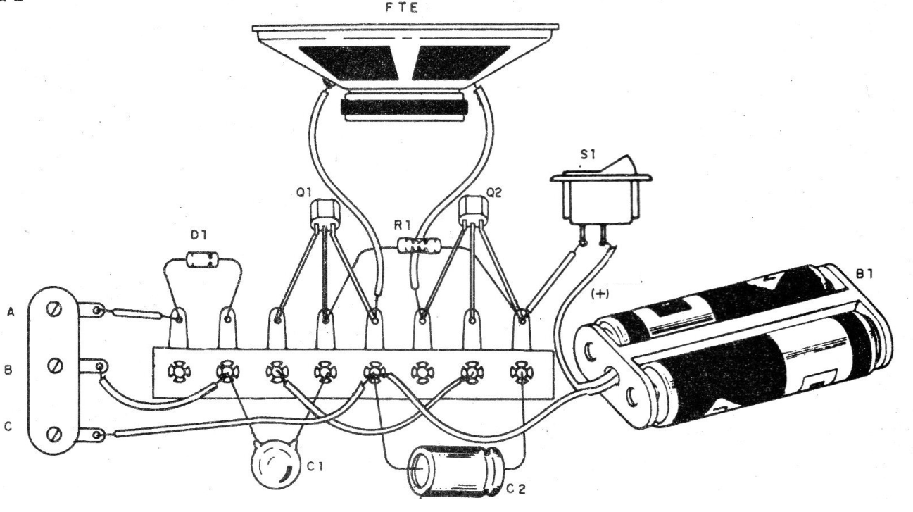
In Figure 2 we have the method of making the assembly based on a common terminal strip.
The single resistor is 1/8 W and its value can be changed to improve gain and fidelity according to the characteristics of the transistors used. The values of this resistor can be between 470 k ohms and 2.2 M ohm The 8-ohm speaker should have dimensions according to the box used.
The capacitor C can be both ceramic and polyester and C2 is an electrolyte of 6 V or more and its value can be between 47 uF and 1000 uF. To complete the assembly, the reader will need one wire with an alligator clip and another with a probe tip. The probe can be of any type, such as those used in multimeters.
The connection of points A, B and C can be done by means of a terminal bar with screws or terminals. To test the instrument, simply connect the alligator clamp to the negative of the batteries of a radon and connect the probe to the B input, lean against the volume potentiometer of this radio.
The signal must be heard clearly from the loudspeaker.


