
With this simple circuit connected at the input of any amplifier, the amplifier becomes a medium-sensitivity radio of good sensitivity. The circuit is simple to mount and can pick up local stations with a small antenna,
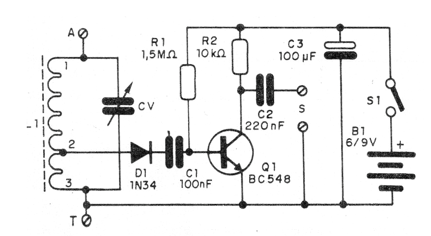
The power supply to the circuit is made with 4 small batteries and the consumption is quite low. In figure 1 we have the tuner circuit.
The assembly can be made on the basis of a terminal strip, as shown in figure 2.
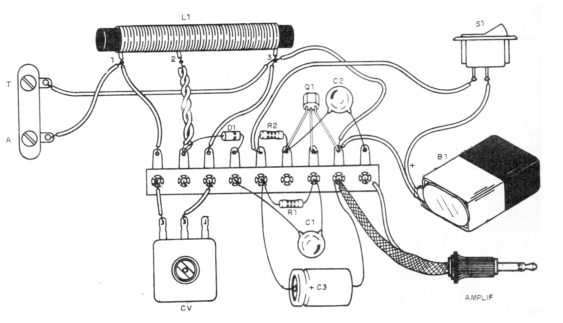
The coil is formed by 30 + 50 turns of common or enamelled wire 28 in a ferrite rod. The variable capacitor can be obtained from an out-of-use AM transistor radio. The cable for input to the amplifier must be shielded and the plug according to the AUX input.
Material list
Q1 - BC548 - NPN general purpose transistor
D1- 1N34 or equivalent - germanium diode
R1- 1.5 M ohms x 1/8 W- resistor - brown, green, green
R2 - 10 k ohms x 1/8 W - resistor - brown, black, orange
C1 - 100 nF - ceramic capacitor
C2- 220 nF - ceramic capacitor or polyester
C3 - 100 uF x 6 V or more - electrolytic capacitor
L1 - Coil - see text
CV- variable capacitor - see text
S1 – On-Off switch
B1 - 6 or 9 V - batteries or battery
Miscellaneous: terminal strip, battery holder or battery connector, shielded wire, plug according to the amplifier, etc.


