
The LM317 (1.5 A) and LM350 (3 A) integrated circuits are adjustable 3-pin voltage regulators that can provide output voltages of 1.25 to 37 V. The LM317 has a version with HV suffix that can provide voltages up to 57 V.
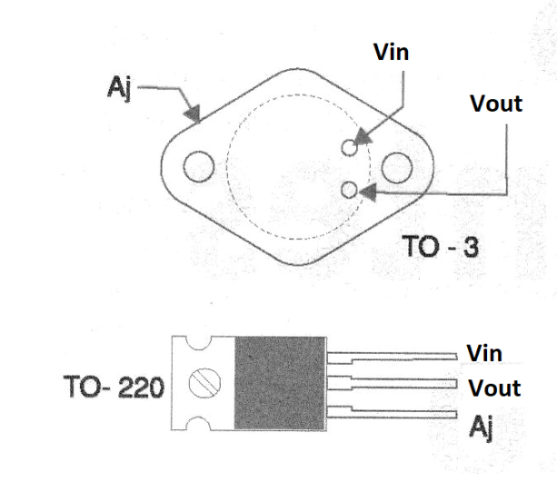
Using these components we can design adjustable power supplies with a minimum of external components. The two integrated circuits are available in both TO-220 (plastic) and TO-3 metallic housings, with the pinouts shown in figure 1.
To implement a variable power supply with these integrated circuits, simply place a variable resistive divider between the output and the adjustment terminal. As the internal reference zener diode is 1.25 V this is the minimum voltage we get.
Larger voltages will be obtained when the resistive divider adds its voltage to this diode. In figure 2 we have a typical power supply based on these two integrated circuits.
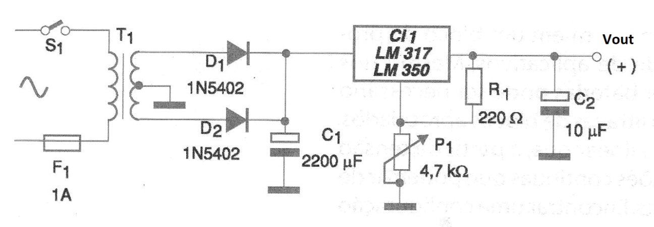
The transformer is chosen so as to have a secondary that provides a voltage at least 2 volt higher than the maximum desired voltage at the output. For the electrolytic filter capacitor it is recommended to use at least 1000 μF for each ampere of the desired current at the source.
Thus, we suggest 2 200 uF for the LM317 and 4 700 uF for the LM350 A, operating at its maximum capacities. The working voltage of this capacitor must be at least 60% greater than the RMS voltage of the transformer secondary used.
In figure 3 we have the suggestion of printed circuit board for the assembly of this source.
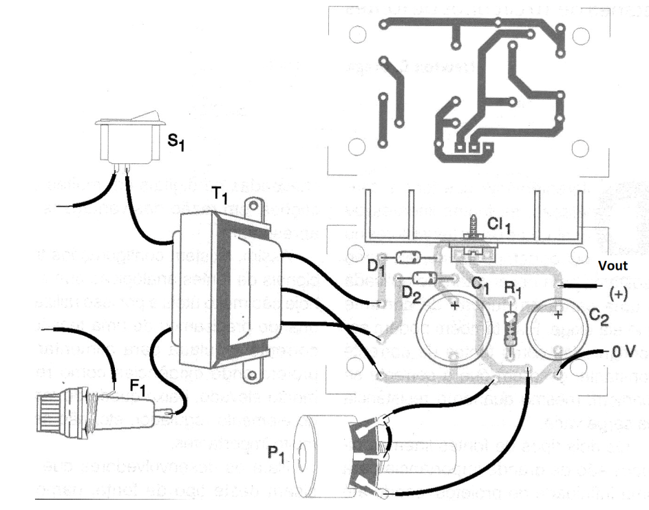
High current tracks should be wide. It is common practice to leave 1 mm wide for each ampere of current, in this type of application. The regulator integrated circuits, for both cases, must be equipped with excellent heat sinks.
Material list
CI-1 - LM317 or LM350 - integrated circuit voltage regulator - see text
D1, D2 - 1N5402 or 1N5404 - rectifier diodes
C1 - 2 200 uF or 4 700 uF - electrolytic capacitor - see text
C2 - 10 uF - electrolytic capacitor - see text
T1 - Transformer - see text
S1 – On/Off switch
F1 - 1 A fuse
Several:
Printed circuit board, heat radiator for transistor, power cable, wires, solder, etc.


