
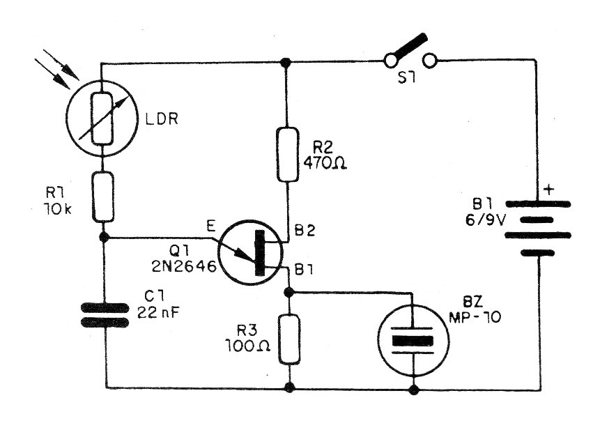
This experimental circuit, or even as a basis for more complex circuits, produces an audio signal that is reproduced in a buzzer and depends on the intensity of the light incident on a sensor. The basic assembly can serve to demonstrate the working principle of LDRs or photo-resistors, which are light sensors.
The circuit is quite simple and can be powered by voltages of 6 to 9 V obtained from batteries or a battery. In figure 1 we have the complete diagram of the oscillator.
The assembly made based on a terminal bridge is shown in figure 2.
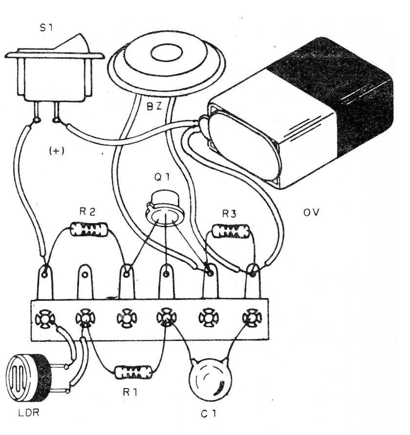
The transducer is a ceramic piezoelectric capsule. The LDR can be of any type and the other components are common.
Material list
Q1 - 2N2646 - unijunction transistor
LDR - common LDR of any type
B1- 6 V or 9 V- 4 batteries or battery
S1 – On-Off switch
BZ - Ceramic capsule
R1- 10 k ohms x 1/8 W- resistor - brown, black, orange
R2 - 470 ohms x 1/8 W- resistor - yellow, violet, brown
R3 - 100 ohms x 1/8 W- resistor - brown, black, brown
C1 - 22 nF - ceramic or polyester capacitor
Miscellaneous: terminal strip, battery connector or battery holder, wires, solder, etc.


