
The purpose of the circuit shown in figure 1 is to generate trains or outputs of rectangular pulses at interval times. The intervals are equal to the duration of the train and are basically determined by C1 and R1. With the values indicated, this time is of the order of 1 second.
Other intervals may be obtained by exchanging these components. The frequency of the pulses is determined by C2 and R2 which in the case is around a few kilohertz. These components may also have their values changed by the application.
The power of the circuit will determine its intensity. Remember that with 10 V power the maximum operating frequency of the circuit is around 7 MHz.
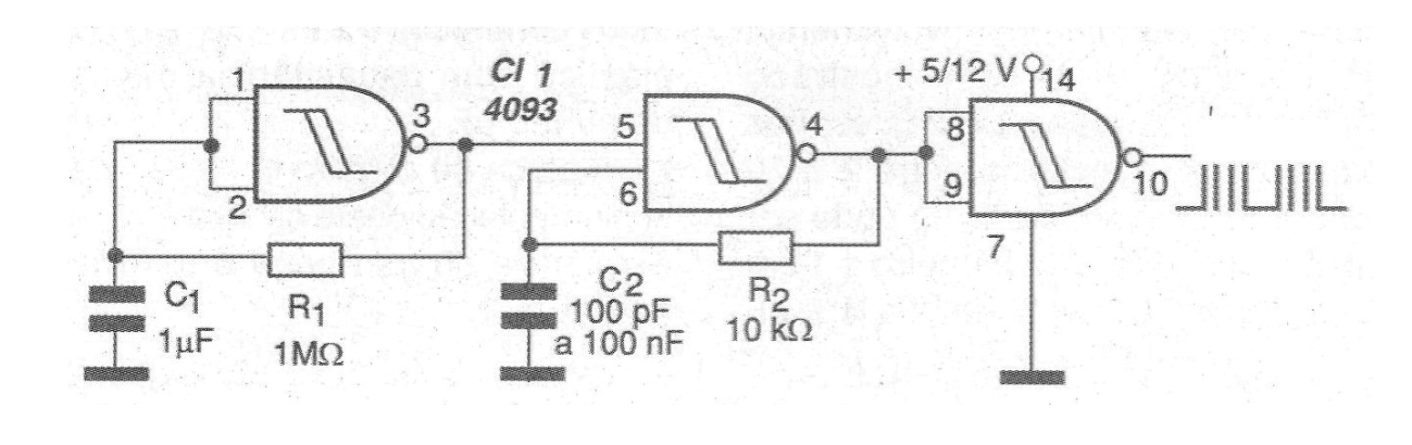
We can use this circuit in the testing of digital data acquisition systems, data transmission line testing and many similar applications.
In Figure 2 we have a printed circuit board for implementation of the device.

Material list
CI-1 - 4093 - CMOS integrated circuit
R1 - 1 M ohm x 1/8 W - resistor
R2 - 10 k ohm x 1/8 W - resistor
C1 - 1 uF - polyester capacitor
C2 - 100 pF at 100 nF - polyester or ceramic capacitor
Several:
Printed circuit board, power supply, wires, solder, etc.


