
If you live far away from the medium-wave stations you like to listen to, needing an external antenna, or even listen to stations in the 2 to 5 MHz range in your locality and still the signals are weak, this circuit can help you .
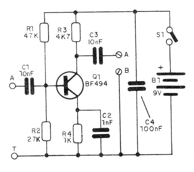
The antenna signals go through an amplification before being brought to the receiver, with a booster that can improve reception quality. The device uses only one transistor and is powered by a 9 V battery or even 9 to 12 V supply. Consumption is very low which means the battery will have great durability. In figure 1 we have the complete diagram of the booster.
In figure 2 we have the assembly using a small terminal strip that must be installed in a plastic box.
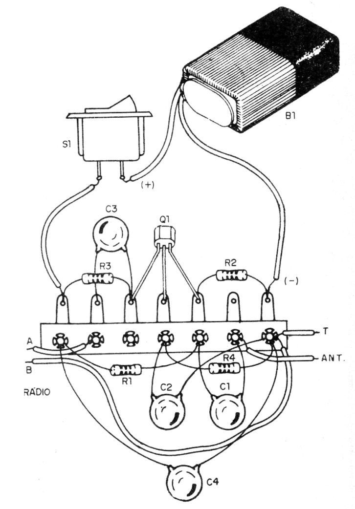
The external antenna can be a wire stretched from 3 to 30 meters in length. Coated wire may be used and earthing is important. It can be a small bar of buried metal or any large metal object.
To connect to the radio, it has no antenna, wrap about 4 to 5 turns of common wire on the radio box thus forming a radiating antenna. Old radios have an A and T (antenna and ground) input that can be used.
The circuit will not work with very weak signals that are covered by noise, as the noise will also be amplified.
Material list
Q1 - BF494 - RF NPN Transistor
S1 - Single switch (optional)
B1 - 9 V - battery
C1, C3-10 nF - ceramic capacitors
C2 - 1 nF - ceramic capacitor
C4 - 100 nF - ceramic capacitor
R1, R3 - 47 k ohm x 1; 8 W - resistor - yellow, violet, orange
R2 - 27k ohm x 1/8 W - resistor - red, violet, orange
R4 - 1k ohm x 1/8 W - resistor - brown, black, red
Miscellaneous: terminal bridge, battery connector, wires, solder, etc.


