
The circuit shown in Figure 1 makes it possible to control direct current motors of various amps from CMOS logic signals.
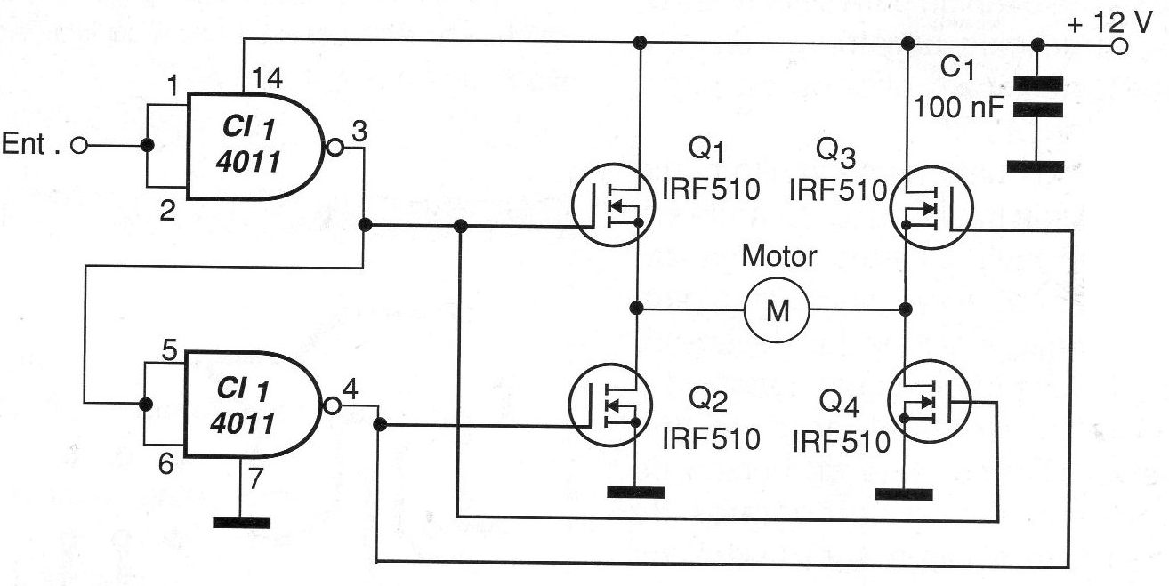
Two of the gates of a 4011 integrated circuit are used as inverters. They are connected in such a way that when one meets the output at high level, the other necessarily meets with the output at the low level.
This way, the power field effect transistors which form the H-bridge lead two by two by establishing different directions of current flow through the motor. With the high level at the input the motor spins in one direction and at the low level in the opposite direction.
The maximum current of the controlled motor depends only on the chosen transistors.
The power supply can be made with voltages different from 12 V, depending on the motor used. With voltages below 9 V, the resistance between the drain and the source of the transistors begins to become sensitive to the losses for the motor.
It may be necessary to connect a capacitor of 1 to 10 uF (depolarized) in parallel with the motor to avoid instabilities caused by the switching of its brushes.
In Figure 2, we have a suggested circuit board for this assembly.
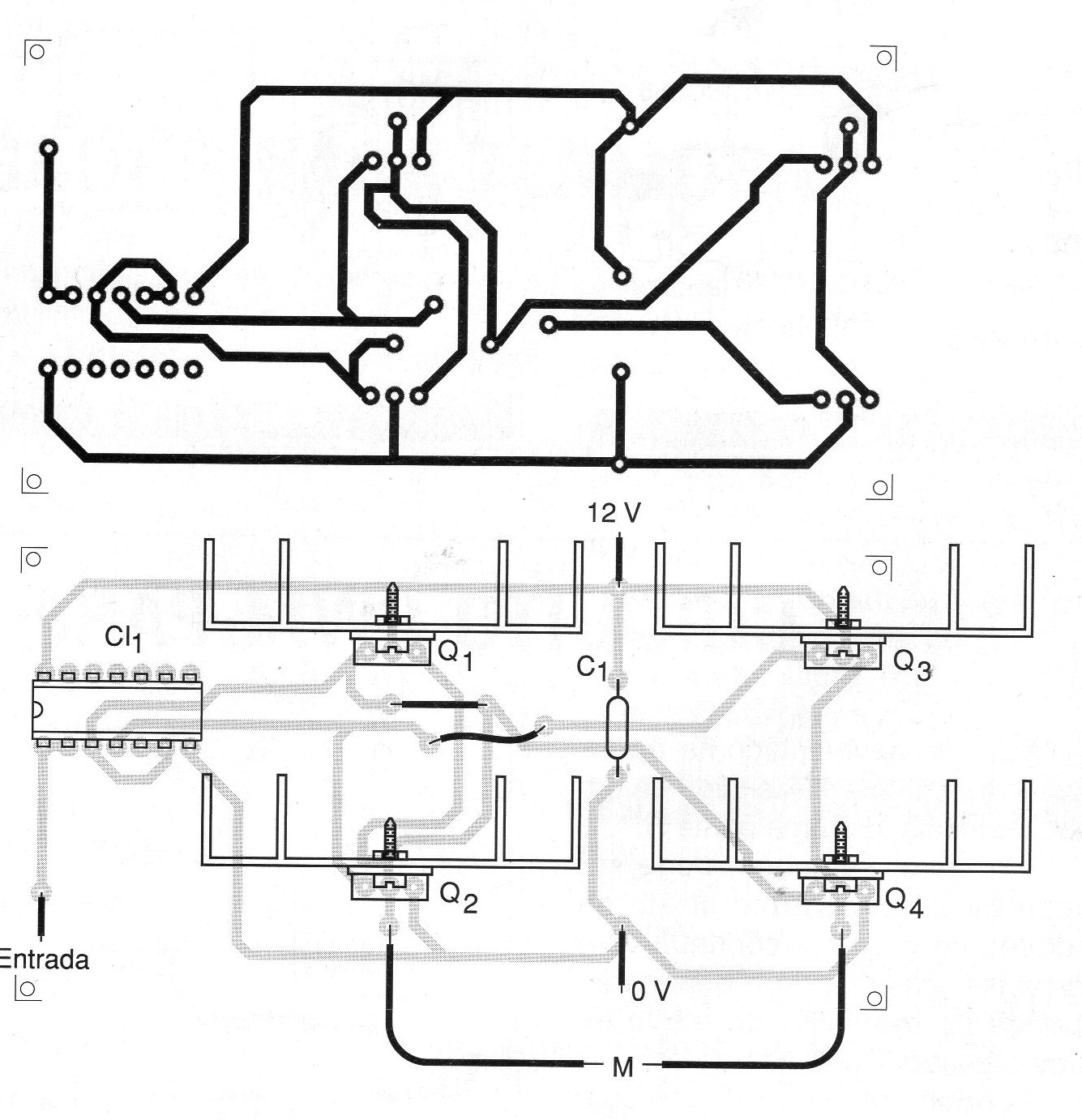
Note that depending on the current required by the motor, the transistors must be fitted with appropriate heat radiators.
LIST OF MATERIALS
CI-1 - 4011 - CMOS integrated circuit
Q1 to Q4 - IRF510 or any N-channel power MOSFETs
C1 - 100 nF - ceramic capacitor
M - motor
Miscellaneous:
Printed circuit board, heat radiators for transistors, wires, welding, etc.


