
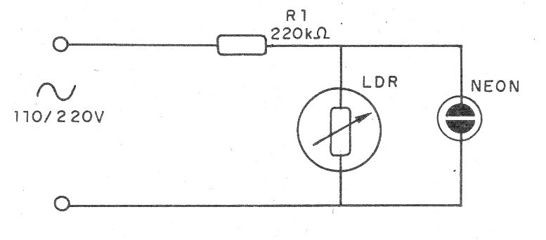
This is an experimental circuit that serves to demonstrate the principle of operation of an LDR in a switch.
When the LDR is in the dark, the neon lamp receives sufficient voltage for the ignition.
However, when the LDR is illuminated, its resistance falls and in series with R1 forms a divider where the voltage becomes less than that required by the ionization of the lamp.
In this way, the neon lamp, which was on, turns off.
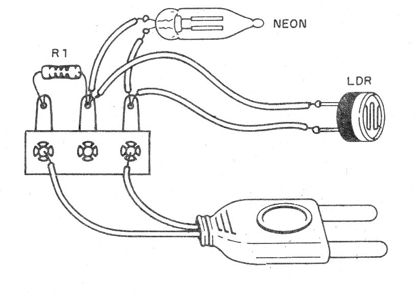
Care must be taken with the assembly, because the circuit is connected directly to the power grid, without insulation.
In figure 1 we have the complete diagram of the apparatus.
In figure 2 we have the aspect of the assembly in a terminal strip, although its implementation can also be done in a matrix of contacts.
Eventually R1 should be changed to achieve the desired performance, but should never be less than 100 k ohms.
Material list
LDR - Common LDR
R1 - 220 k ohms x 1/8 W - resistor - red, red, yellow
NE-1 - common neon lamp
Several:
Power cable, wires, terminal strip, solder, etc.


