
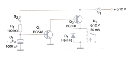
The circuit shown in Figure 1 drives a relay a certain time after the key S2 is closed. The drive time depends on the value of C1 and will be between a few seconds to a few minutes.
We can drive R1 directly with the signal from an external circuit such as a TTL output, CMOS or even a remote sensor.
• Operate automatism some time after switching on the switch S2 - the switch S2 can be a limit switch or a sensor.
• Disconnect devices after the drive, using a relay with the NF function.
• Detect function locking on a machine by activating an alarm system.
• Activate an alarm system after a few seconds until a few minutes after the activation of S2 - Car alarm, for example.
• Delay machine functions from the on / off switch.
Constructive Details:
The relay must have an operating voltage equal to the supply voltage used in the circuit. The resistor R1 may be increased depending on the gain of the transistors Q1 and Q2 to the point where the drive is possible. Increasing the value of R1 enables an increase in the delay time.
In figure 2 we have the printed circuit board for assembly using a DIL-based relay.
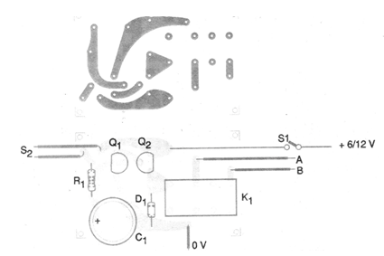
For other types of relay the board must be changed.
We observe that the drained current in the standby condition is extremely low, less than 1 mA depending on the leaks of Q2.
The maximum value of the capacitor will be determined by its possible leakage. We do not recommend values above 1000 uF.
Material list
Semiconductors:
Q1 - BC548 or equivalent - NPN general purpose transistor
Q2 - BC558 or equivalent - general purpose PNP transistor
D1 - 1N4148 - general purpose diode
Resistor: (5%, 1/8 W)
R1 - 100k ohms
Capacitor:
C1 - 1 to 1000 uF x 12 V - electrolytic
Several:
K1 - Sensitive relay of 6 or 12 V x 50 mA
S1, S2 - Single switches
Printed circuit board, wires, solder, etc.


