
This version of the skill game known as Nerve-Test gives no shock to anyone but is also impossible to fool. An electronic circuit fires at the slightest touch of the wire on the ring and thus remains for a few seconds.
Simple to assemble, this is a design for beginners. The Nerve-Test game, for those who do not know, consists of a tortuous wire and a ring. The player must pass the ring through the tortuous wire without touching each other, because if this happens the electronic circuit will fire and the alarm will ring.
At each touch the player loses a point or is disqualified, according to the previous combination. It wins whoever can pass the ring to the end of the wire without letting the alarm ring, or play less number of times.
The circuit presented is very simple and works with only two small batteries.
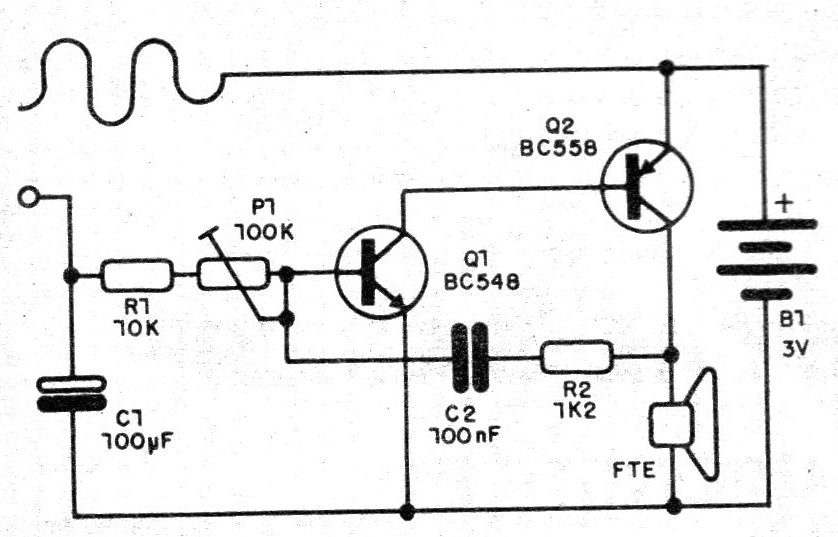
The base of the circuit is a simple audio oscillator whose sound emitted basically depends on the capacitor C2. The C1 capacitor is used to determine the trigger time for each touch, and can be between 22 and 220 uF. The ideal is 100 uF, when the touch has enough time just to be perceived.
When the wire touches the ring, even briefly, this capacitor charges and then slowly discharges through the oscillator circuit, which goes into action producing a sound that mimics a siren. The P1 trimpot is used to adjust the ring time and pitch of the sound being output.
ASSEMBLY
We begin by giving the complete diagram of the apparatus in figure 1.
Assembly, as indicated for beginners, can be carried out on a terminal strip. (figure 2).
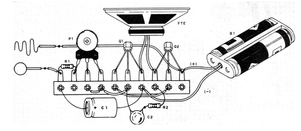
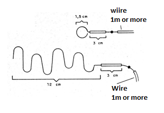
This strip will be fixed later inside a plastic box. An important point of the assembly is the pair formed by the loop and the tortuous wire. We use common bonding wire (16 or 14AWG). The cover of the wire is not completely removed, since we can leave a piece in each to serve as a cable, where the player will hold the two pieces.
In figure 3 we show how these two elements are prepared.
In the assembly it is important to observe the polarity of the electrolytic capacitor. You can experiment with several values for this component, depending on the time you want to sound. The working voltage must be greater than 3 V for this component.
The other capacitor may have values between 47 and 100 nF, with either ceramic types, the marking of which may be 473 or 104, and polyester, the marking of which may be 0.047 or 0.1 uF.
The resistors are all 1/8 or ¼ W and the speaker is small 8 ohm. Even the transistors admit equivalents. For Q1 any general purpose silicon NPN and any general purpose silicon PNP can be tested for Q1. Try the ones you have on your scrap but respect the order of the transmitter (E), collector (C) and base (B) connection, which means you must know how to identify these terminals.
For batteries, use a proper holder observing the polarity of the connection.
PROOF AND USE
Insert the batteries into the cradle. We do not need to use a general switch, since keeping the wire and the ring apart there is practically no energy consumption. Only when storing the device remove the batteries from the stand for extra safety. Put the wire on the ring and adjust P1 so that the sound emitted is of pleasant tone and duration according to the taste of the players.
Release the wire, detaching it from the ring and see for how long the sound persists. If you want to increase this time, increase the value of C1.
Then just kidding, checking who gets pass the ring through the wire without letting the device touch.
MATERIAL LIST
Q1 - BC548 or equivalent - NPN silicon transistor
Q2 - BC558 or equivalent PNP silicon transistors
FTE - 5 cm x 89 speaker
B1 - 3 V - 2 small batteries
C1 - 100 uF «electrolytic capacitor
C2 -100 nF or 47 nF - ceramic or polyester capacitor
P1 - 100 k - trimpot
R1 - 10 k - resistor (brown, black, orange)
R2 - 1k2 - resistor (brown, red, red)
Miscellaneous: thick wire to make wire and ring, terminal bridge, holder for 2 small cells, wires, box for assembly, welding, etc.


