
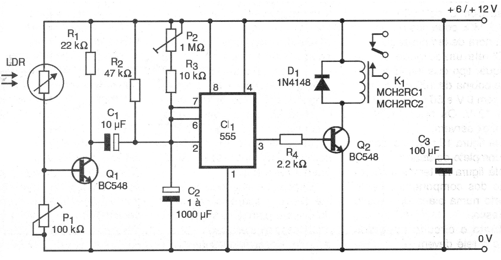
When a pulse of light strikes the LDR, this circuit triggers a monostable 555 timer that drives a relay for a time set by P2.
The time can vary from a few seconds to several minutes depending on the capacitor C2.
The entire circuit is based on a monostable 555 being shown in figure 1.
The printed circuit board for this assembly is shown in figure 2.
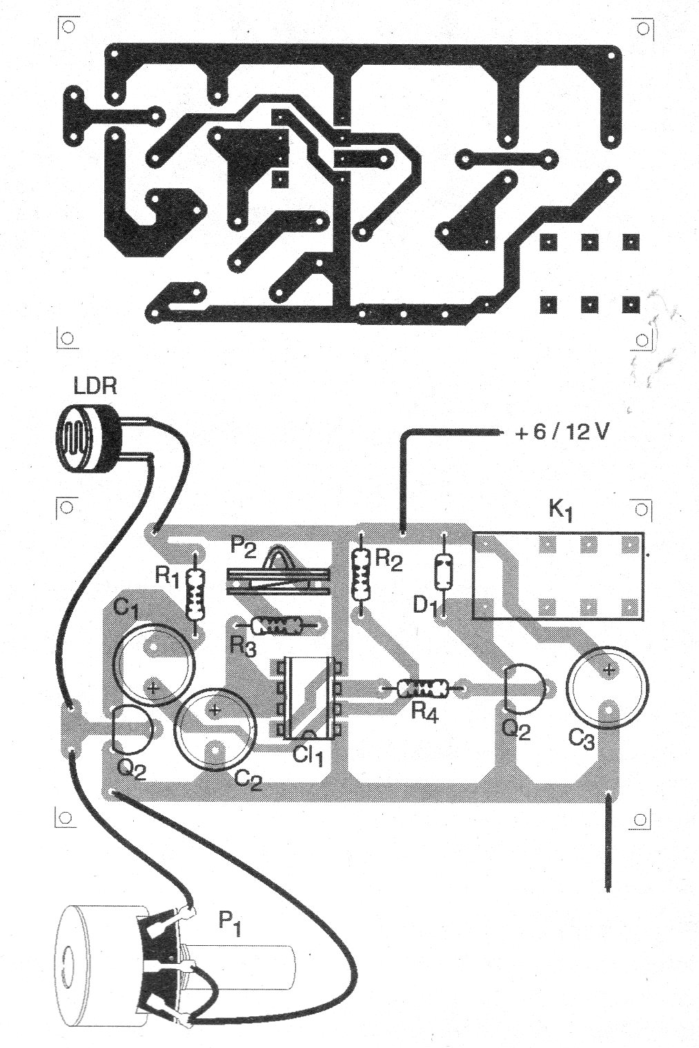
On assembly, observe the positions of transistors and the integrated circuit as well as the polarity of the diode and the electrolytic capacitors.
The resistors are 1/8 W with any tolerance and the electrolytic capacitors to 12 V or more.
The relay is of the type sensitive with triggering current up to 100 mA and the LDR is of the ordinary round type.
Material list
CI-1 - 555 - integrated circuit
Q1, Q2 - BC548 - general purpose NPN transistors
D1 - 1N4148 - general purpose diode
LDR - round common LDR
K1 - 6 or 12 V sensitive relay
P1 - 100 k ohms - potentiometer
C1 - 10 uF - electrolytic capacitor
C2 - 1 to 1000 uF - electrolytic capacitor
C3 - 100 uF - electrolytic capacitor
R1 - 22 k ohms - resistor - red, red, orange
R2 - 10 k ohms - resistor - brown, black, orange
R3 - 2k2 ohms - resistor - network, network, network
Several:
Printed circuit board, power supply, mounting box, wires, solder, etc.


