
The circuit shown in figure 1 turns off a load after a time elapsed from the moment its power is established.
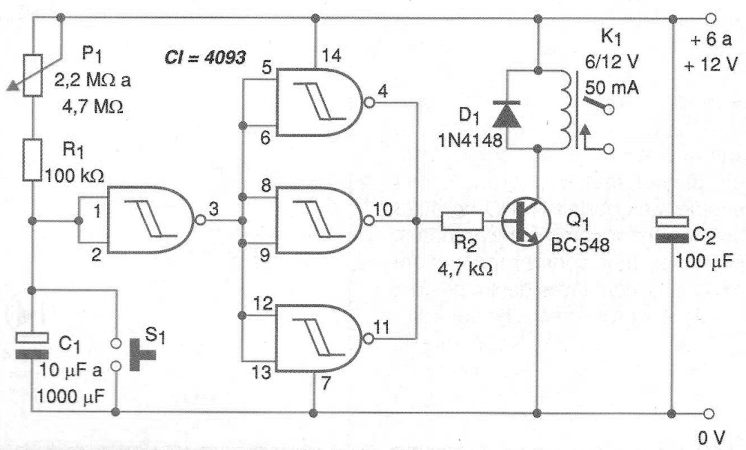
The time interval depends on the time constant of the RC circuit formed by the potentiometer P1, resistor R1 and the capacitor C1 which can have values of up to 2 200 uF. Using higher values the circuit can reach timings longer than one hour.
Among the possible applications we suggest automatic shut-off systems or automatic timed activation of various devices. The type of controlled load depends exclusively on the contact capacity of the relay used.
For applications where a battery is used as the power source, low power relays should be used. The S1 pressure switch is optional as a reset and also to ensure that at start-up we have a complete timing with the capacitor load from zero.
In figure 2 we have a printed circuit board for the assembly of this timer.
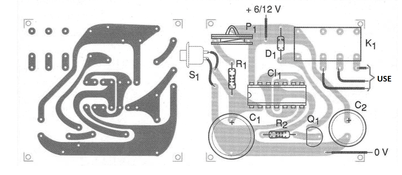
This board provides for the use of relays with DIL socket. For higher current relays, the design of the board must be redone according to the arrangement of the terminals or even to be mounted outside the board.
MATERIAL LIST
CI-1 - 4093 - CMOS integrated circuit
Q1 - BC548 or equivalent - NPN general purpose transistor
D1 - 1N4148 - general purpose diode
R1 - 100 k ohm x 1/8 W - resistor - brown, black, yellow
R2 - 4.7 k ohm x 1/8 W - resistor - yellow, violet, red
P1 - 1 M ohm at 4.7 M ohms - potentiometer
C1 - 10 uF at 2 200 uF x 16 V - electrolytic capacitor
C2 - 100 uF x 16 V - electrolytic capacitor
K1 - 6 or 12 V x 50 mA or more sensitive - relay
S1 – Push button - optional - see text
Several:
Printed circuit board, relay socket (optional), wires, solder, etc.


