
The production of radio signals or electromagnetic waves, which can propagate through space and carry information, is so simple that few know that it can be achieved with only three improvised components. This possibility can be explored in demonstrations such as school work, science classes and science fairs.
Signals, which can traverse obstacles such as planks, wooden partitions and walls, can be picked up on a common, transistorized portable radio. experimentally the assembler can demonstrate the effects quoted, but as a practical montage it serves to transmit code signals to a friend who is in an adjacent apartment or room, through the wall.
The transmitter is extremely simple, as we said, and as a receiver any portable radio can be used.
Operation:
Very rapid current interruptions can generate oscillations of electrical charges that produce radio waves, that is, electromagnetic waves of high frequencies, that propagate through space with the speed of light.
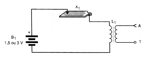
We can produce such "vibrations" in a very simple way by rubbing a wire attached to a pile in a common file. As an inductive "load" to reinforce the oscillations, that is, to produce the desired signals, we have a coil wound on a ferrite rod.
In fact, this circuit does not generate a fixed frequency signal. Its signals spread over a wide range of frequencies, thus producing a "radio noise" or EMI (Electromagnetic Interference). Its operation as transmitter really for long range is prohibited as it interferes in many types of communication devices.
However, this was the first device used by Marconi, Landel de Moura and other researchers who eventually invented the radio.
In our system we will use as antenna a simple piece of wire about 50 cm in length, and for demonstrations with small reaches, even this will not be necessary, since the signals will not go beyond a few meters. This will prevent interference with radios and connected TVs in the vicinity.
This is, of course, a device intended only for demonstrations and short-range experiments. In figure 1 we have the complete diagram of our elementary transmitter.
In figure 2 we have the general appearance of the assembly.
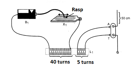
The coil is wrapped in a ferrite rod (which can be harnessed from any old unused transistor radios) and can be either cylindrical or flat. This coil has a winding formed by approximately 40 turns of common or enameled wire of any thickness and another winding with 5 turns of the same wire.
The wires connected to the battery are soldered at their terminals. If enameled wires are used they should be scraped at the welding point.
To operate the transmitter is simple:
Connect an AM radio out of station tuned anywhere in the range (1 to 2 meters). Scrape the yarn in the file. Noise should be transmitted to the radio.
The reader will see that these signals can cross obstacles, because if the radio is on the other side of a wall they will still be picked up.
The encoding of the signals, for me messages can be transmitted, can be done in Morse. In this condition a "shaving" of short duration means a point and a longer shave a stroke. Dots and dashes are combined to form letters, numbers, and graphic signs.
For an operation with a slightly larger range, the antenna is a piece of ordinary wire approximately 50 cm to 1 meter. Grounding can be done on any larger metal object.
As explained, this transmitter does not emit fixed frequency signals but rather a noise. In this way, do not connect it to external or long antennas. The signals can also be tuned to the shortwave range from 3 MHz to 10 MHz if the player has a receiver that has these bands.
When not in use, do not let the cord touch the file, as there is no emission, the battery quickly spends due to excessive current.
MATERIAL LIST
B1 - 1 large battery
X1 - 1 file
L1 - Coil - see text
Several:
Antenna / ground terminal, enameled wire, wires, solder, etc.


