
If you are a shortwave listener or simply tune in to some medium-wave station, but near your home there is a powerful transmitter from a local station that interferes with the entire range, which we describe is a circuit that rejects the signal from the interfering station.
The filter we describe eliminates the strong signal from a nearby station in the middle wave band, which may be spreading across the spectrum by interfering with other bands, for example shortwave bands.
Just tune into CV the undesired station that your signal will be attenuated to the point of not harming listening to weaker stations in the medium and short wave bands.
What happens is that a very strong signal tends to spread over a larger band since the receiver's circuits can not block it. With the help of the additional tuned circuit we described, we can reduce the signal strength before it enters the receiver.
In figure 1 we have the complete diagram of the filter.
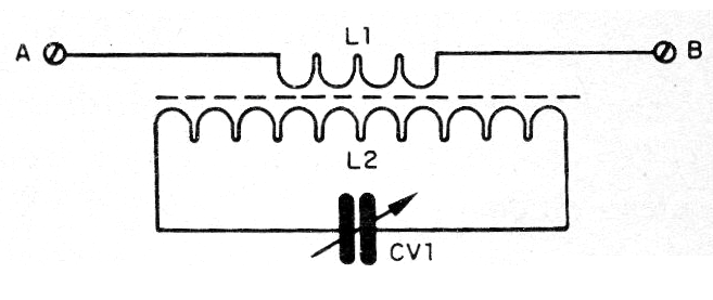
Only two components are used and the assembly aspect is shown in figure 2.
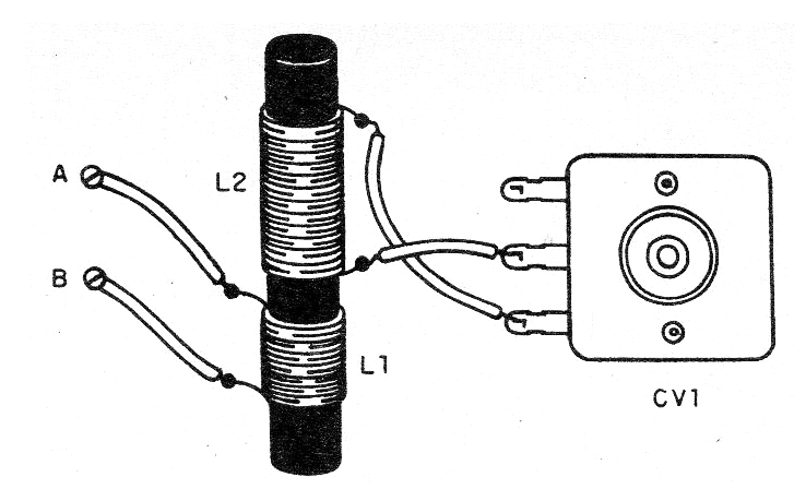
The coil L1 is formed by 20 turns of wire 22 to 28 AWG while L2 consists of 100 turns of the same wire, the two coiled in a ferrite rod 10 to 20 cm long and about 1 cm in diameter.
CV1 is a variable capacitor that can be obtained on an out-of-use transistor AM radio.
The assembly can be mounted in a shielded box for greater efficiency only with the points A and B accessible to connect in the external circuit. A is connected to the external antenna and B to the antenna input of the interfered radio.
Once installed, set CV1 to get rejection of the interfering station.
Parts list
L1, L2 - coils - see text
CV1 - AM variable radio capacitor
Miscellaneous:
Ferrite core, enamelled wire, solder, etc.


