
The simple project presented uses only one transistor and its assembly offers no difficulty at all, even for beginners. It is a continuity tester of great utility on the bench because it can test components of various types, wires, connections, and more.
The use of a transistor in a circuit like this allows a very large reduction in the test current, which guarantees the integrity of the components under test, especially if they are sensitive. On the other hand, relatively high resistances, which would not be detected by a common tester with directly connected bulbs or LEDs, can be accused thanks to the gain of the transistor. The tester we describe works with 4 small cells, being able to detect resistances up to 100 k ohm with ease.
How it works
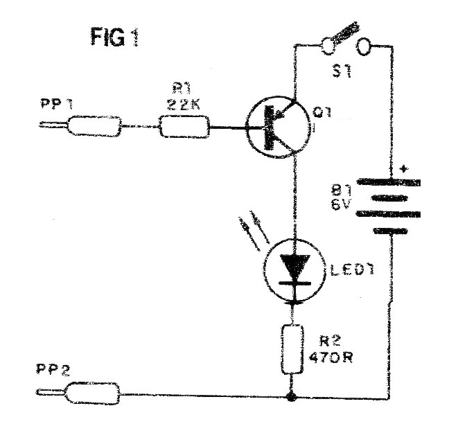
The component in evidence is wired between the collector and the base of the transistor, thus providing the polarization for conduction. If the resistance of the component is low enough to let the polarizing current pass, the transistor will turn on and the LED will light up, indicating the fact.
The transistor may have gains in the range of 30 to 800, which will result in sensitivity allowing the LED to light with resistances of approximately 20 k to 1 M ohm approximately.
Any transistor PNP can be used in the assembly, such as 2SB175, AC128, OC74 (old), or modern types such as BC307, BC557, BC558, etc. The important thing is to check your position in the assembly according to the connection points of the transmitter (E), collector (C) and base (B). Old appliances, out of use, are excellent source of transistors that can be availed in this assembly.
Assembly
We begin by showing in diagram 1 the simple component tester diagram.
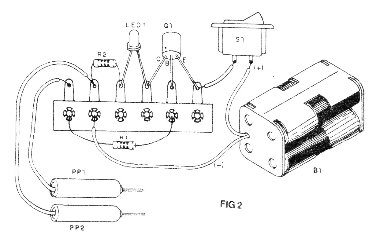
The assembly can be installed in a small plastic box and even switch S1 can be eliminated, since the PP1 and PP2 probes are separated, there is no power consumption. The LED should be on the outside of the box and may be of any color. Probes can be improvised with large nails if you do not want to use a commercial pair of the type found in multimeters.
Test and Use
After completing the assembly, insert the batteries into the holder and turn S1 on. If the LED lights up, it signals that the transistor is faulty or inverted. It may also occur that the transistor is not of the indicated type (PNP). The probes should be separated.
By connecting the probes, the LED should light up. If this does not occur, either the transistor is open (bad) or is of the type that is not for the project. It may also occur that it is inverted.
To use the tester simply lean the probes on the terminals of the components to be tested. The component must be off the circuit or the device it is in must be switched off. If the LED lights up there is continuity and the resistance is less than the value taken as the base. Remember that depending on the component, for it to be good, there must be high or low resistance.
Material list
Q1 - Any PNP transistor - see text
LED - common red or other colored LED
S1 - Single switch
B1 - 6 V - 4 small batteries
R1 - 22k ohm x 1/8 W - resistor - red, red, orange
R2 - 470 ohm x 1/8 W - resistor - yellow, violet, brown
Miscellaneous:
Terminal bridge, test leads (PP1 and PP2), holder of 4 small batteries, wires, solder, etc.
Note: This project, for its simplicity, is recommended for electronic courses at all levels, from elementary and middle school in initial activities (STEM), as well as in technical courses. Assembly can also be done very easily in contact array, universal board or even a printed circuit board created by the student.


