
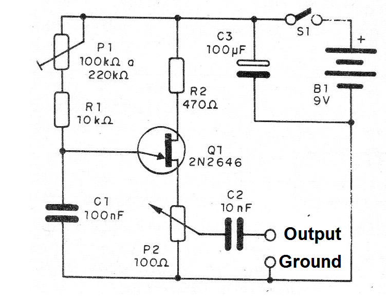
This signal injector consists of a single transistor relaxation oscillator. The circuit has frequency control and also a signal strength control.
The frequency range generated goes from about 100 Hz to about 2 kHz but can be changed by replacing C1. The circuit, however, will not oscillate above about 200 kHz.
The power is supplied by a 9 V battery with very low power consumption. The device can be installed in a plastic case for easer use.
In figure 1 we have the complete diagram of the injector. The assembly on a terminal strip is shown in figure 2.
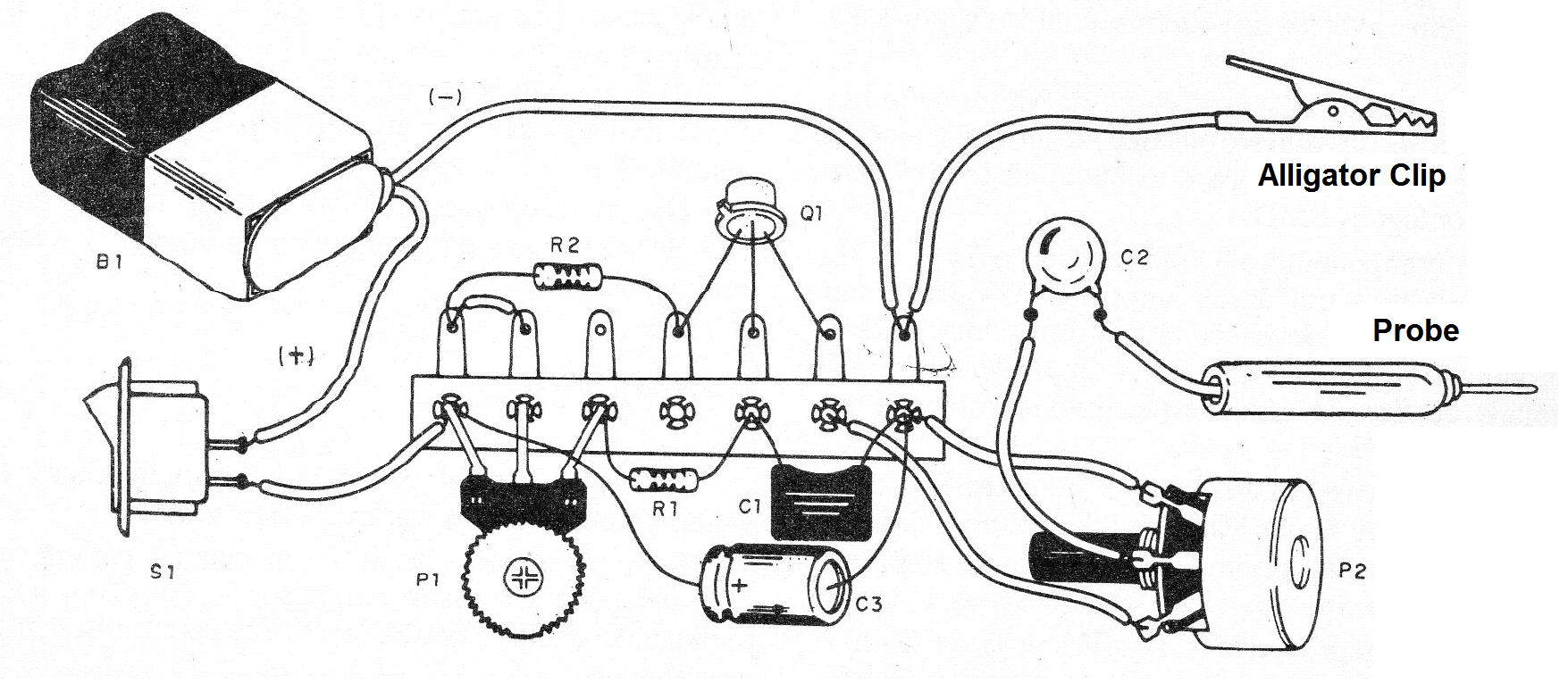
The transistor must be 2N2646 and the potentiometers can be both linear and logarithmic. The resistors are 1/8 W or ¼ W and the capacitors are common.
For the exits we suggest the use of the alligator clip and a probe.
Material list:
Q1 - 2N2646 - unijunction transistor
S1 - Single switch
B1 - 9 V - battery
P1 - 100 or 220 k ohm - potentiometer or trimpot
P2 - 100 ohm - potentiometer
R1 - 10 k ohm - resistor - brown, black, orange
R2 - 470 ohm- resistor - yellow, violet, brown
C1- 100 nF- ceramic or polyester capacitor
C2 - 10 nF- ceramic capacitor or polyester
C3 - 100 uF - electrolytic capacitor - 12 or 16 V
Miscellaneous:
Terminal strip, mounting box, battery connector, buttons for potentiometers, wires, solder, etc.


