
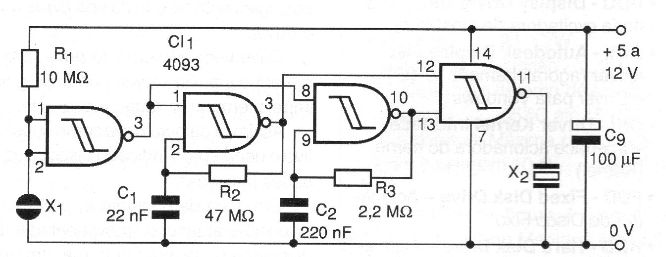
The circuit shown in figure 1 generates an intermittent tone on a piezoelectric transducer when the touch sensor is activated. The tone frequency is basically given by R2 which can have values between 10 k ohms and 100 k ohms. It will be interesting to determine the value that produces the loudest sound in the transducer since many of them have their maximum output at a resonance frequency around 4 kHz.
The time off depends on R3 and C2 which can also be changed over a good range of values. The ceramic transducer provides good audio power for battery-powered and 9 V battery applications, since it has low power consumption.
However, for applications where greater power is required, or even where the reader wishes to use a speaker, the power steps of Figure 2 may be used.
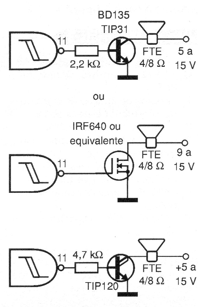
For sources above 9 V the transistor must be provided with a heat radiator. The touch sensor consists of two separate metal pads that must be played simultaneously.
Material list
CI-1 - 4093 - Integrated Circuit CMOS
X1 - Touch sensor
R1 - 10 k ohm x 1/8 W - resistor - brown, black, orange
R2 - 47 k ohm x 1/8 W - resistor - yellow, violet, orange
R3 - 2.2 M ohm x 1/8 W - resistor - red, red, green
C1 - 22 nF - ceramic or polyester capacitor
C2 - 220 nF to 470 nF - ceramic or polyester capacitor
C3 - 100 uF x 16 V - electrolytic capacitor
BZ - High impedance piezoelectric transducer


