
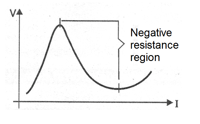
Neon lamps are active elements of circuits that are characterized by presenting a region of negative resistance in its characteristic curve.
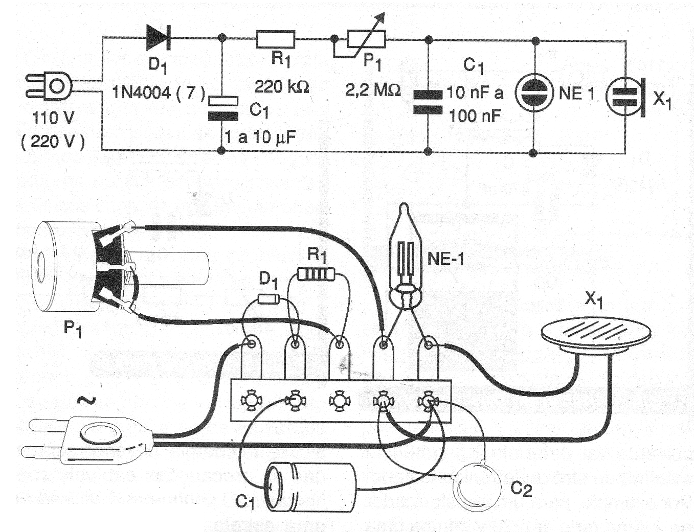
This region allows its utilization in a low frequency (audio) oscillator circuit as shown in figure 1.
This circuit generates a tone that will be reproduced on a high impedance (piezoelectric) transducer and whose frequency can be adjusted in the potentiometer.
With the use of a larger capacitor, in the range of 470 nF to 2.2 uF the circuit becomes a very low frequency oscillator, or blinker.
Circuit power must be supplied with voltage above 90 V, as most ordinary neon lamps need at least 80 V to ionize. Any common lamp can be used and the circuit will operate on both 110 V and 220 V mains.
The capacitor C1 forming the source may be from 1 to 10 uF with a working voltage of 200 V if the grid is 110 V and 400 V if the grid is 220 V.
As it is an experimental circuit, its assembly can be implemented as shown in figure 2.
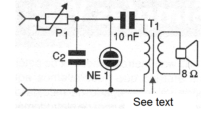
To use a loudspeaker, a small output transformer must be included, as shown in figure 3. This transformer, taken from an old transistor radio, must have a primary winding with at least 1000 ohms of impedance.
Material list
D1-1N4004 (110V) or 1N4007 (220V)
C1 - 1 to 10 uF x 200 (400 V)
C2 - 10 nF to 100 nF - c polyester sprayer to 100 V or more
R1 - 220 k ohms x 1/8 W - resistor - red, red, yellow
P1 - 2.2 M ohms - potentiometer
NE-1 - common neon lamp - NE-2H or equivalent
X1 - High impedance piezoelectric transducer
Miscellaneous:
Power cable, terminal bridge, wires, solder, etc.


