
The oscillator shown in figure 1 has its output formed by pulses that can be modulated by a voltage applied to the input (V control).
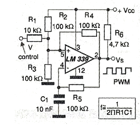
The central frequency of the signal is determined by R5 and C1, according to the formula next to the diagram. This formula is approximate and the tolerances of the components must be taken into account. The control voltage should vary between 0 and the supply voltage of the circuit which may typically be between 6 and 12 V.
The output signal is formed by rectangular pulses. Note the need for a pull-up resistor at the output, since the LM339 has open collector output transistors.
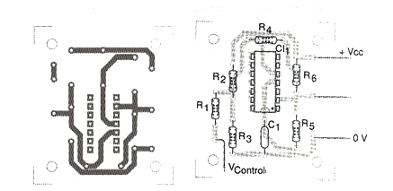
The circuit can generate signals up to about 1 MHz. The control signal may come from resistive sensors or other sources. In figure 2 we have a suggestion of printed circuit board, remembering with the other comparators of the LM339 can be used for other purposes, since they are independent.
The circuit does not require a symmetrical power supply.
Material list
CI-1 - LM339 - Quad Voltage Comparator
R1 - 10 k ohm x 1/8 W - resistor
R2, R3, R4, R5 - 100 k ohm x 1/8 W - resistors
R6 - 4.7 k ohm x 1/8 W - resistor
C1 - 10 nF - capacitor
More:
Printed circuit board, power supply, wires, solder, etc.


