
This experimental MW radio receiver can pick up the most powerful local stations. You will need a 2 to 20 meter antenna for good results. Grounding to any large metal object such as a window or door is important;
As a headset we can use high impedance types or even a small speaker with the output transformer. Resistor R1 should be obtained experimentally around the indicated value for greater sensitivity. In figure 1 we have the complete diagram of the receiver.
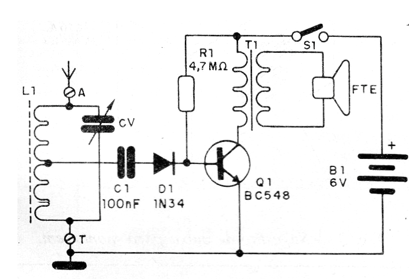
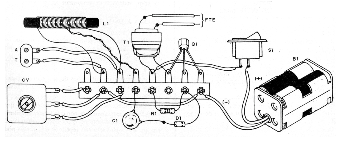
L1 consists of 30 + 50 turns 28 of wire on a ferrite rod. The tap is made from the 30 counted turns of the ground side. CV is a variable obtained on older transistor radios, as well as the speaker and the output transformer. The other components are common. In figure 2 we have the mounting on a terminal strip.
Material list
Q1- BC548 - General Purpose NPN Transistor
D1-1N34 or equivalent - germanium diode
L1 - Antenna coil - see text
CV - Variable Capacitor - see text
T1 - Output transformer - see text
FTE - 4 or 8 ohm - Small Speaker
S1 - Single Switch
B1 - 6 V - 4 small batteries
C1 - 100 nF - Ceramic or Polyester Capacitor
R1 - 4.7 M ohm x 1/8 W - resistor - yellow, violet, green
Miscellaneous: terminal strip, battery holder, antenna, wire, solder, etc.


