
The circuit shown in figure 1 can control the speed of a motor connected to a H-bridge.
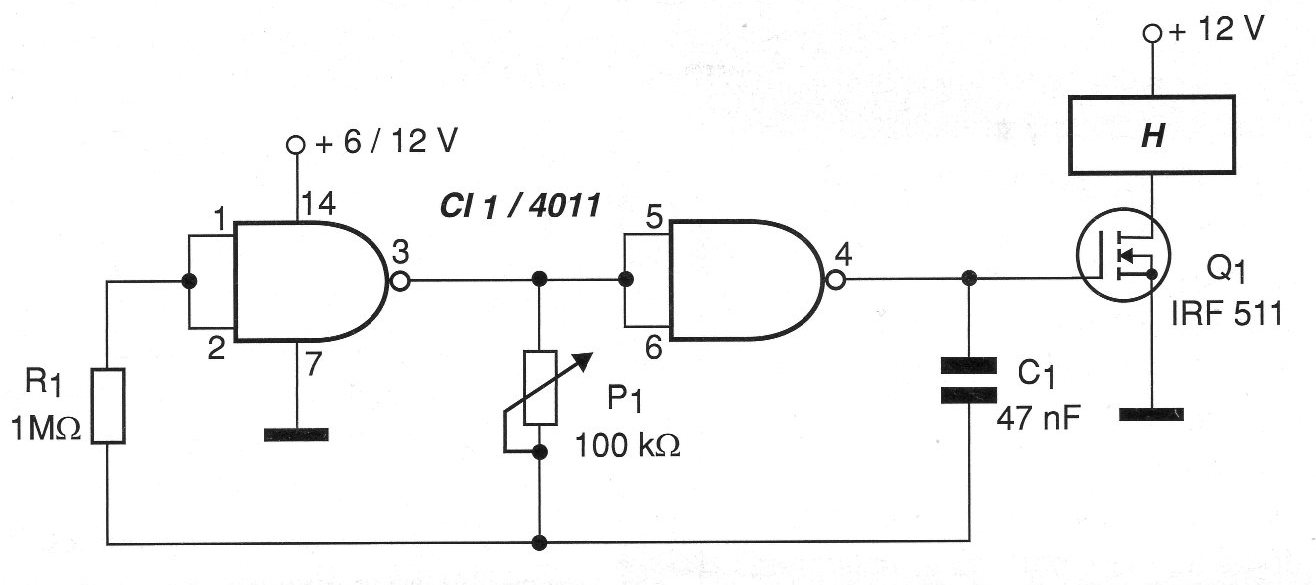
This circuit can also be employed in direct control of DC motors with maximum currents that depend only on the field effect transistor used. Currents of up to 10 A can be controlled with motors not only 12 V, but even with higher voltages. The control range must be obtained experimentally as a function of the value of capacitor c1. Depending on the motor, value changes of this component may be necessary to avoid vibration of the engine at very low speeds.
The power supply of the 4011 should be 6 to 12 volts with a common ground relative to the power supply to the motor, which may have different voltages. In figure 2 we have a suggestion of printed circuit board for the assembly of this control.
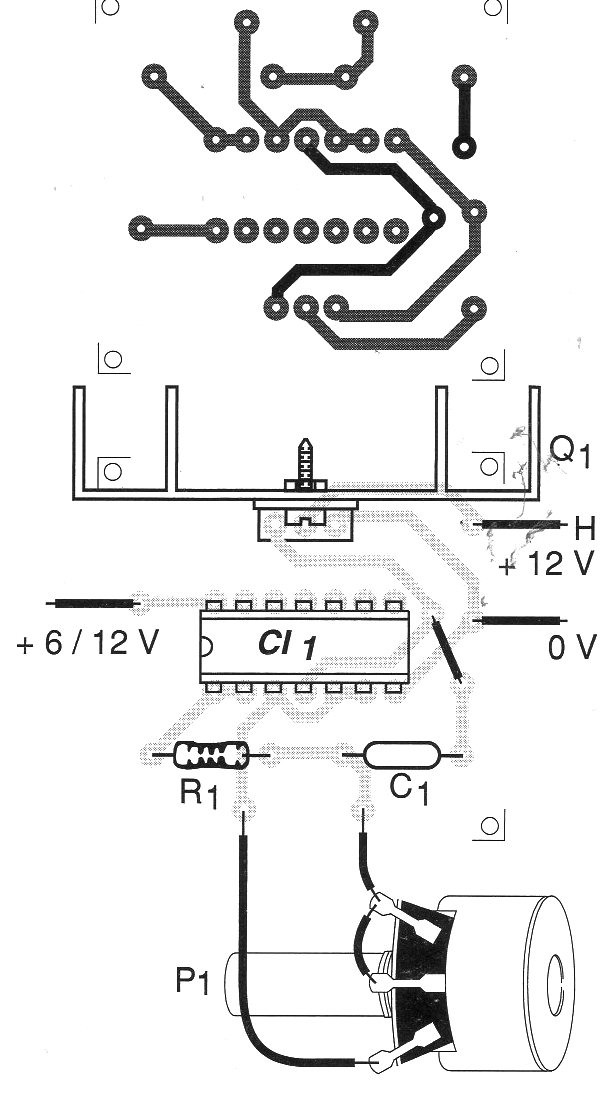
The field effect transistor can be any type of N channel and must be fitted with a heat radiator compatible with the controlled current.
MATERIAL LIST
CI-1 - 4011 - CMOS integrated circuit
Q1 - IRF511 - power field effect transistor - or equivalent
R1 - 1 M ohm x 1/8 W - resistor - brown, black, green
P1 - 100 k ohm - potentiometer
C1 - 47 nF - ceramic or polyester capacitor
More:
Printed circuit board, heat radiator, wires, solder, etc.


