
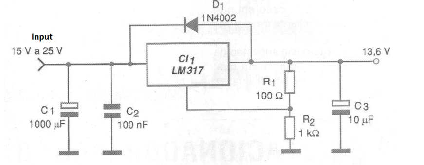
The circuit shown in figure 1 is ideally suited to obtain a regulated voltage of 13.6 V for power to the bench of mobile equipment, usually operating with automotive batteries. The maximum output current is 1.5 A, determined by the integrated circuit LM317. The integrated circuit must be mounted on a good heat radiator.
The electrolytic capacitors must have working voltages of at least 25 V. It is convenient to protect the input of the circuit through a fuse. The accuracy of the output voltage will depend on the accuracy of the resistors R1 and R2.
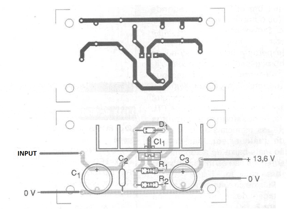
In Figure 2 we have the printed circuit board for implementation of this voltage regulator.
Material list
CI-1 - LM317 T - integrated voltage regulator circuit
D1 - 1N4002 - silicon diode
R1 - 100 ohm x ½ W - resistor
R2 - 1 k ohm x 1/8 W - resistor
C1 - 1000 uF x 25 V - electrolytic capacitor
C2 - 100 nF - ceramic capacitor
C3 - 10 uF x 16 V - electrolytic capacitor
Several:
Printed circuit board, heat radiator, wires, solder, etc.


