
To generate signals in a range of frequencies between a few tens of kilohertz to 30 or 40 MHz, the Hartley oscillator shown in figure 1 fits perfectly.
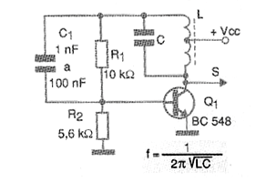
In this circuit is the resonant pair LC that determine the frequency of operation. For high frequencies we can use either an adjustable core coil or a variable capacitor. The values of C1 are chosen according to the range of frequencies to be generated, as well as the coil, which must be wound on a ferrite rod for frequencies below 20 MHz and without a core above 20 MHz.
The table below gives the number of turns in a rod 1 cm in diameter x 10 cm in length as well as the value of C1. The value of C is also given
For the values of resistors indicated in the diagram the power can be between 3 and 12 V. The formula next to the diagram allows to calculate more accurately the frequency of operation.
In figure 2 we have a suggestion of printed circuit board for the assembly of this oscillator.
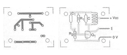
We observed that for frequencies above 1 MHz the capacitors must be ceramic.
Material list
Q1 - BC548 or equivalent - NPN general purpose transistor
C1 - 1 nF at 100 nF - capacitor - see table
C - capacitor - see table
L - coil according to frequency - see table
R1 - 10 k ohm x 1/8 W - resistor
R2 - 5.6 k ohm x 1/8 W - resistor
Several:
Printed circuit board, wires, ferrite core for coil, solder, etc.
| Frequency | |
| C1 | |
| L | |
| C | |
| 10 kHz to 100 kHz | |
| 22 a 100 nF | |
| 200 - 500 turns | |
| 10 a 100 nF | |
| 100 kHz to 1 MHz | |
| 4,7 nF a 22 nF | |
| 100 - 200 turns | |
| 100 pF a 10 nF | |
| 1 MHz to 10 MHz | |
| 2,2 nF a 4,7 nF | |
| 20 - 100 turns | |
| 10 pF a 1 nF | |
| 10 MHz to 30 Mhz | |
| 470 pF a 1 nF | |
| 8 - 20 turns | |
| 4,7 pF a 10 pF |


