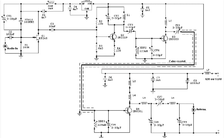
The transmitter presented by our contributing reader Adriano Muniz Moura has a power of 10 watts and can be used to help your community spread news, warnings, etc. However, to use this type of equipment, it is advisable to read the legal restrictions for this type of transmitter. The transistor used as the main oscillator was a BF245 which is a field effect transistor, and all other transistors must have heat sinks and for better stability the final output transistor 2N6081 must have a small fan to reduce its temperature. Power must come from an external source with a voltage between 12V and 13.8V with a current of at least 10A.
The coils are made as follows:
L1 and L2 are formed by 8 turns of 18 wire with a diameter of 1 cm without a core.
L3 and L4 are formed by 12 turns of wire 16 with a diameter of 1.5 cm, also without a core.
L5 and L6 are formed by 7 turns of wire 14 with 2cm diameter without core
L7 is formed by 15 turns of 18 wire with 1cm in diameter made without a core.
The transmitter frequency is adjusted by choosing crystal oscillator1 and setting CV1. Coils L5, L6 and trimmers CV8 and CV9 form an output filter to minimize possible interference. The coaxial cable that carries the signal from the exciting stage to the final stage must be a maximum of 25 cm and the mesh can be grounded at any negative point in the circuit. The capacitors are ceramic except for the adjustable capacitors, which must be plastic or porcelain. The plate used for assembly must be made of good quality fiberglass. To adjust the transmitter, a frequency meter and a phantom load must be used and for use with a coupled antenna, an R.O.E. meter must be used.