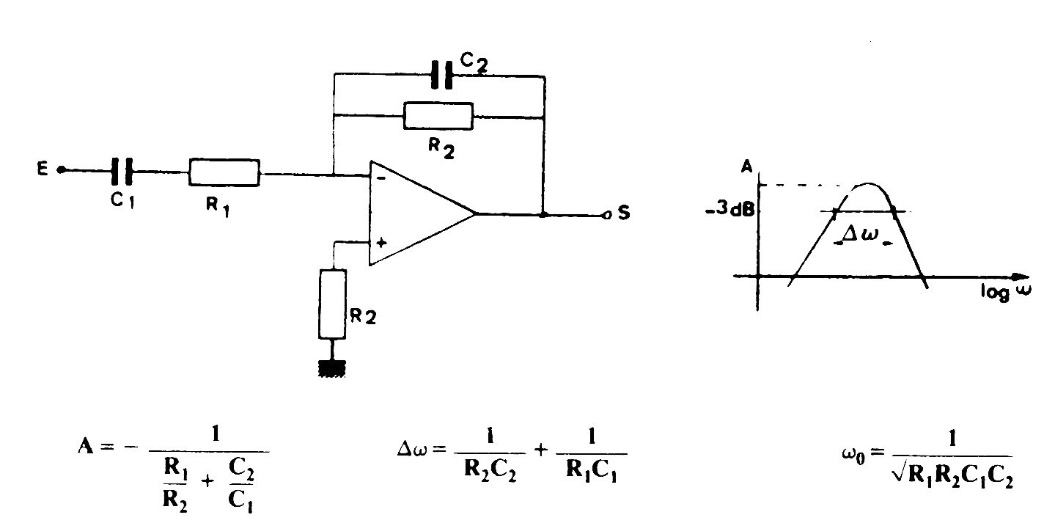
This filter, found in an old manual, has characteristics of reduced overvoltage given by the graph next to the diagram. Formulas for component calculations are given next to the diagram.
| Clique na imagem para ampliar |

This filter, found in an old manual, has characteristics of reduced overvoltage given by the graph next to the diagram. Formulas for component calculations are given next to the diagram.


