
ART2969S ART165
It is not always possible to interconnect an audio signal source with the amplifier or equipment where we want to reproduce the signals from this source using wires. This can happen, for example, if the signal source is on one side of a street and the amplifier or playback/recording location is on the other, as shown in Figure 1.
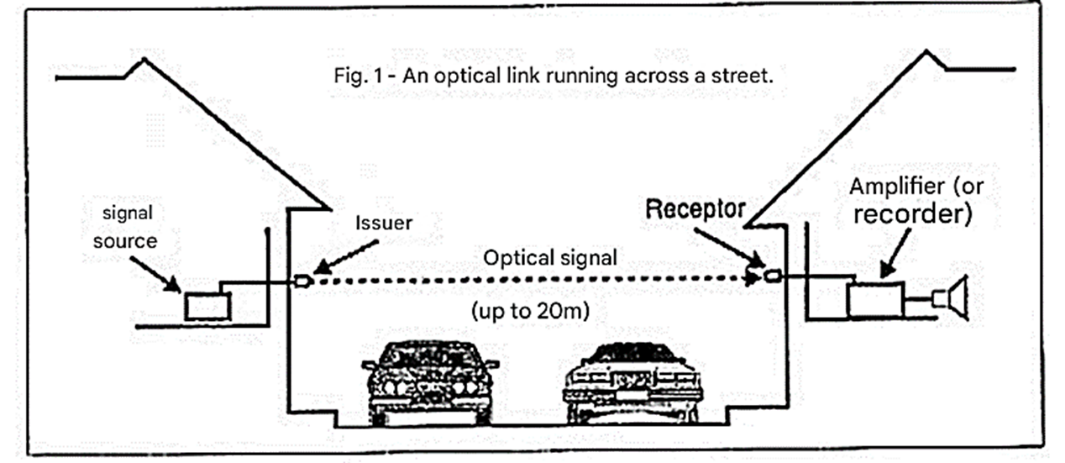
In this case, we can solve the problem of the impossibility of running a cable using a fairly simple optical link, which is precisely described in this article. What is done is to modulate a set of LEDs (red or infrared) with this signal and receive the modulated light from the other side of the street, applying the signal directly to the sound equipment. Without lenses we can transmit the signals over a few meters, but with converging lenses in front of the LEDs and the sensor, this range can become much greater, as shown in Figure 2.
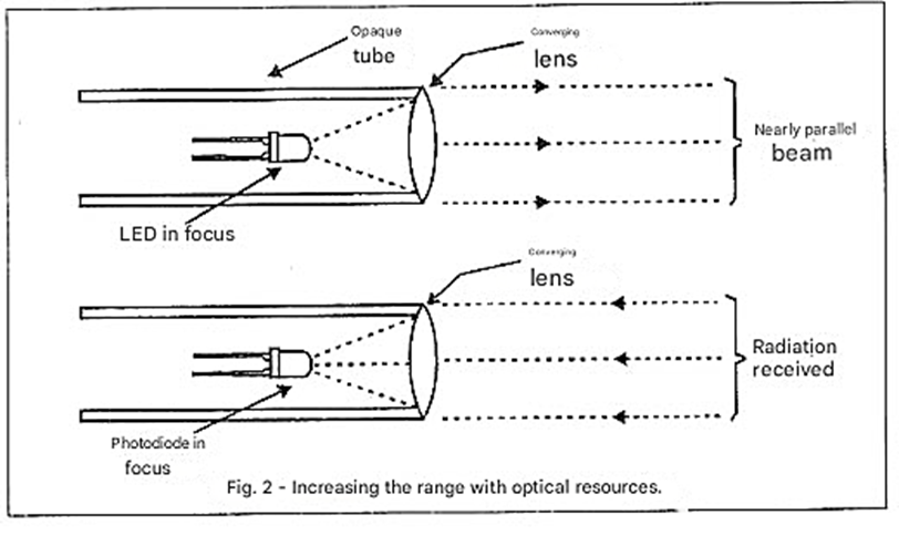
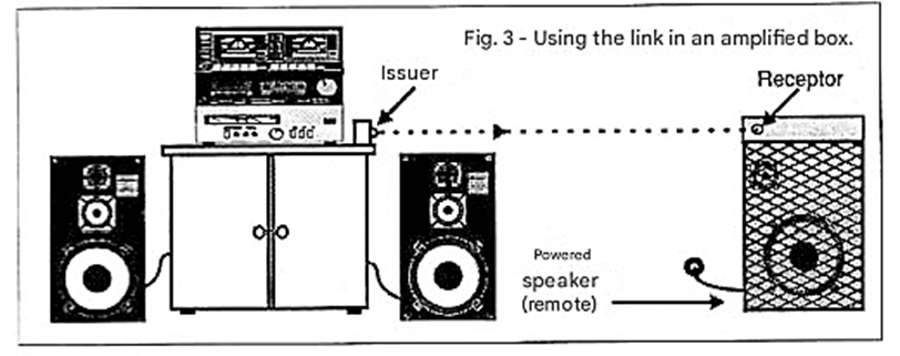
There is even the possibility of placing the sensor in the eyepiece of a telescope or binoculars, in which case the range can be surprisingly long, exceeding 1 km. Another application is within a small environment, where we can have an amplified box that receives the signal from one of the channels of a stereo system without the need for wires, as shown in Figure 3.
Finally, we have a more personal application where the audio signal from a television modulates the transmitter on a television and is received by the receiver where it excites a headphone, as shown in Figure 4.
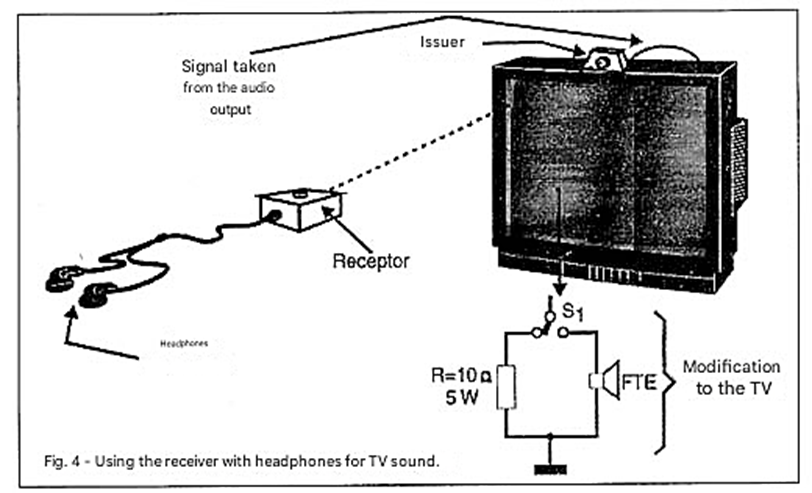
In this application, we can use the pair to listen to TV programs on headphones without disturbing other people in the house, especially if this happens late at night.
HOW IT WORKS
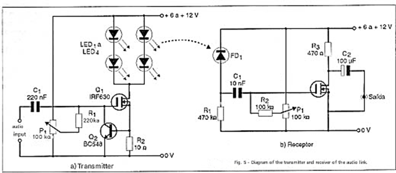
Both the transmitter and the receiver use power field-effect transistors, which, thanks to their use in switched-mode power supplies for computers, televisions, and video monitors, are becoming increasingly cheaper and easier to find. In the transmitter, a single power FET excites a battery of 4 LEDs emitting visible or infrared light from the audio signal, which can be obtained from an amplifier or a television (or other signal source).
The FET's bias is adjusted by P1 so that it conducts current to a degree that, with the audio signal, we have oscillations in both half-cycles with equal intensity. This adjustment can be done "by ear" or, if the reader prefers, by connecting an oscilloscope to the transistor's drain. Transistor Q2 acts as a current source, biasing the field-effect transistor to achieve greater linearity with the audio signals.
In the receiver, we have basically the same configuration, with the difference that the signal to be amplified comes from a photodiode (or phototransistor). In this case, we also have the adjustment of the FET bias using a trim pot. With the help of an oscilloscope or even by ear, we must make the adjustment to obtain an output signal with minimal distortion. The output is made through the transistor's drain and can be applied directly to the input of any audio amplifier or even to medium-impedance headphones (between 100 and 1000 ohms). Both circuits can be powered with voltages from 6 to 12 volts, but the higher value (12 V) is recommended for the transmitter to obtain greater range.
ASSEMBLY
Figure 5 shows the diagrams for both the transmitter and receiver of the optical link.
The component layout on printed circuit boards for the transmitter and receiver is shown in Figure 6.
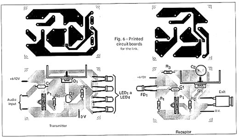
The power field-effect transistors accept equivalents and do not need heat sinks. In fact, any N-channel power field-effect transistor can be used in this project without problems. The resistors are 1/8W or larger, and both P1 and P2 are common potentiometers or trimpots. The transmitter LEDs can be red or infrared, since the receiver's efficiency is higher in these colors. They should be mounted together and, if possible, in a tube to direct the light to the receiver. Placing a converging lens in front of the tube can concentrate its emission and thus obtain greater range; the same applies to the receiver.
The receiver sensor is a common photodiode or even a phototransistor. It would also be interesting to mount the sensor in a tube with a lens, not only to obtain greater directivity but also to avoid light sources that could cause interference. Fluorescent lamps should be avoided as they induce strong hum in the circuit. The audio signal output should be made with shielded wire if the receiver is connected to the high-impedance input of an amplifier. If connected to headphones, ordinary wires can be used.
For the transmitter, a simple, unregulated power supply is sufficient, and for the receiver, either batteries or a power supply can be used. In both cases, filtering is important to prevent hum. Power field-effect transistors accept equivalents and do not need heat sinks. In fact, any N-channel power field-effect transistor can be used in this project without problems.
The resistors are 1/8W or larger, and both P1 and P2 are common potentiometers or trimpots. The transmitter LEDs can be red or infrared, since the receiver's efficiency is higher in these colors. They should be mounted together and, if possible, in a tube to direct the light to the receiver. Placing a converging lens in front of the tube can concentrate its emission and thus obtain greater range; the same applies to the receiver. The receiver sensor is a common photodiode or even a phototransistor. It will also be interesting to mount the sensor in a tube with a lens not only to obtain greater directivity but also to avoid light sources that may cause interference.
In particular, fluorescent lamps should be avoided as they induce strong hum in the circuit. The audio signal output should be shielded if the receiver is connected to the high-impedance input of an amplifier. If connected to headphones, regular wires can be used. For the transmitter, a simple, unregulated power supply is sufficient, and for the receiver, either batteries or a power supply can be used. In both cases, filtering is important to prevent hum.
TESTING AND USE
Connect the output of an amplifier or sound system to the transmitter, and the output of the receiver to the AUX input of any audio amplifier, positioning them as shown in Figure 7.
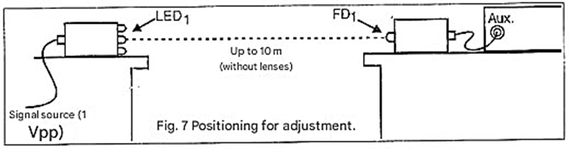
Adjust the volume of the system serving as the signal source and the volume of the receiver. Then, adjust both P1 on the transmitter and the receiver to obtain the cleanest possible sound reproduction. Once the operation is verified, you can install both devices in plastic boxes and use them as you wish.
Parts List
a) Transmitter
Semiconductors:
Q1 - IRF630 or equivalent - power field-effect transistor
Q1 - BC548 or equivalent - general-purpose NPN transistor
LED1 to LED4 - common red or infrared LEDs - see text
Resistors: 91/8W, 5%)
R1 - 220 k ohms
R2 - 10 ohms
P1 - 100 k ohms - trimpot or potentiometer
Capacitors:
C1 - 220 nF - ceramic or polyester
Miscellaneous:
Printed circuit board, power supply, wires, solder, etc.
b) Receiver
Semiconductors:
Q1 - IRF630 or equivalent - power field-effect transistor
FD1 - Photodiode or phototransistor - see text
Resistors: (1/8W, 5%)
R1 - 470 k ohms
R2 - 100 k ohms
R3 - 470 ohms
P1 - 100 k ohms - trimpot or potentiometer
Capacitors:
C1 - 100 nF - ceramic or polyester
C2 - 100 uF/16V - electrolytic
Miscellaneous:
Printed circuit board, power supply, enclosure, wires, solder, etc.


