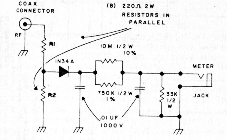
The resistors R1 and R2 consist of 8 220 ohms x 2 W resistors connected in parallel. The dissipation must be higher for high transmitter power. The indicator can be the multimeter.
| Clique na imagem para ampliar |

The resistors R1 and R2 consist of 8 220 ohms x 2 W resistors connected in parallel. The dissipation must be higher for high transmitter power. The indicator can be the multimeter.


