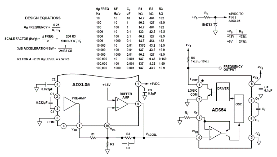
The circuit was suggested by Analog Devices (www.analog.com) in its Application Note AN-411 and consists of a circuit in which the output frequency varies directly with the acceleration applied to the sensor. This circuit is shown in the figure. Power can be supplied with voltages from simple sources between 9 V and 12 V. The sensor is a +/-5g ADXL05 that converts any acceleration applied directly into a voltage. This voltage is then applied to an AD654, which consists of a low-cost voltage-frequency converter. The table next to the diagram gives component values for various output frequency ranges. In this table we also have a breakdown of acceleration in terms of Hertz/g. The output voltage at pin 8 of the ADXL05 is +2.5 V without acceleration and varies 200 mV above or below this value for each 1g of acceleration detected. In the same diagram we have the formulas that make it possible to calculate the components to obtain specific characteristics for the project. In the design, the resistors must be precision and R1a must be approximately 50% of the value of R1b. High precision resistors can be used for calibration and then replaced with types with 1% tolerance.


