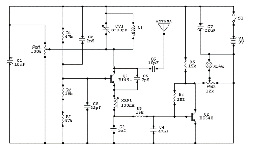
The receiver shown above was sent in by contributing reader Adriano Muniz Moura and is used for the common FM band from 88MHz to 108MHz. It can be used for experiments in schools. The circuit is based on its oscillator, which is formed by the coil L1, CV1 and the radio frequency shock XRF1. The resistors are 1/8 w and the capacitors are for 25v and the L1 coil is formed by 4 turns of 20 wire with 8.5mm diameter without core and the trimmer is 3-30pF made of good quality plastic. The BF494 transistor can be replaced by the BF495 and pot 1 is used to adjust the sensitivity of the circuit, which must be mounted on a fiberglass board and the connections must be as short as possible. The antenna used is a piece of rigid wire approximately 65cm long and if the receiver picks up a lot of noise during use, the 10pF capacitor C6 can be replaced by another 15pF capacitor also made of disc-type ceramic. The power supply used can be anyone that has good filtering and a minimum current of 500mA with a voltage of 9 to 12V. The RF shock (XRF1) must be a commercial type of 100mH to 120mH or 60 turns of 32 wire on a 100k resistor. This project can be used as a basis for larger receivers or as a basis for VHF receivers (with few changes).