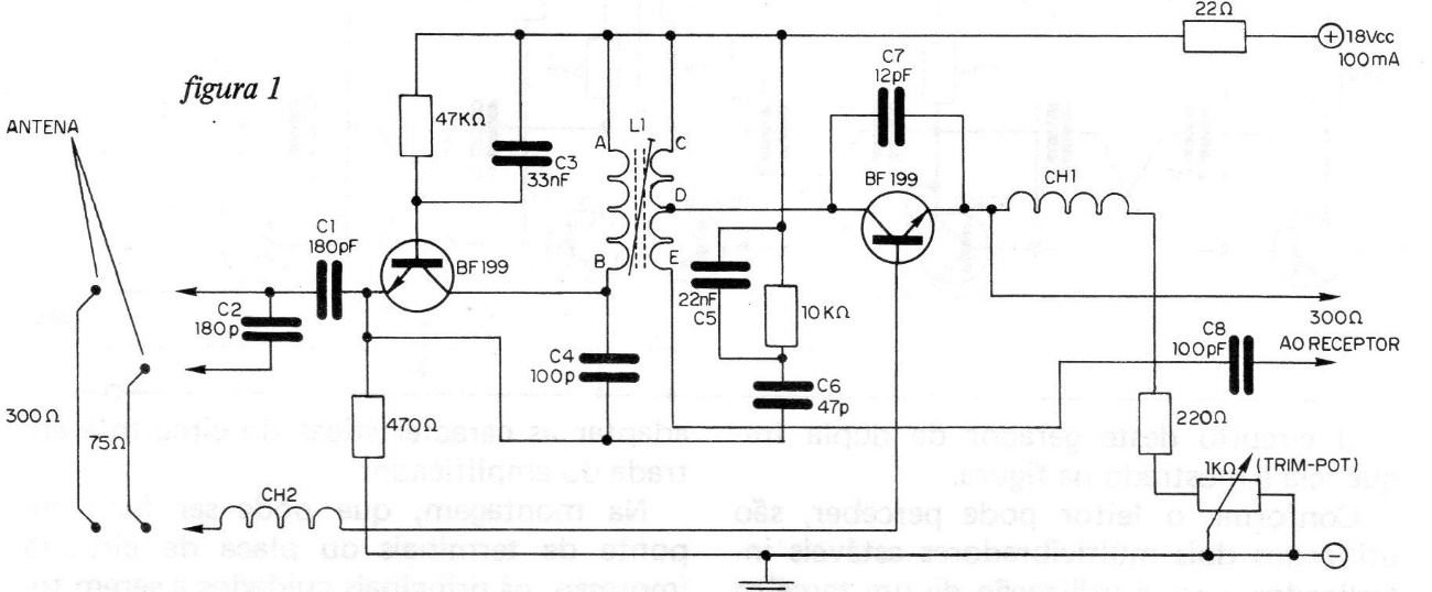
The signals from weak TV, FM and VHF stations can be amplified to assist their reception in locations away from broadcasters. The circuit shown in the figure uses two high frequency transistors, type BF199, and can be interleaved between the TV, FM or VHF receiver antenna and the receiver, this via a 75 or 300ohms cable. According to the author of the project, stations that in normal conditions arrive very weak, can be received with excellent quality of sound or image (as the case may be), as if they were next to home. The only adjustment necessary for the operation of the device is the L1 core, for maximum signal strength at the desired station. The trimpot helps to eliminate local noise or interference. The components are not critical, but when assembling, if bridged, care must be taken that the connections are as short as possible between all parts. L1 is an oscillating coil for FM (green color), while CH1 and CH2 are RF shocks wrapped in a 100k x 1/8 W resistor. The number of turns in each is 32 and the wire used is AWG 34. The resistors are all de W with 10% tolerance. The amplifier requires a special source, which is shown in the same figure. This power supply uses a 9 + 9 V x 100 mA transformer and 4 bridge diodes, in order to obtain approximately 18 V. at its output. Capacitors C1 and C2 are ceramic. C3 and C5 are metallized polyester capacitors, while the others are ceramic, disc type.