You connect this small FM transmitter to the output of the sound pickup of your guitar, acoustic guitar or other instrument and that's it: the sound can be transferred to a wireless amplifier, placed nearby. In addition to the mobility that this means, there is less chance of picking up hum or noise.
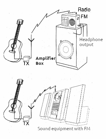
As for the transmitter, we teach you how to assemble it in this article, and the receiver can be any FM radio connected to the amplifier used, or it can be your own sound equipment, set to a frequency free from the FM band. The transmitter should be mounted in a small box that will be attached to the musician's waist and its antenna is a piece of wire about 10 cm long, which gives the system a range of around 20 meters.
How it Works
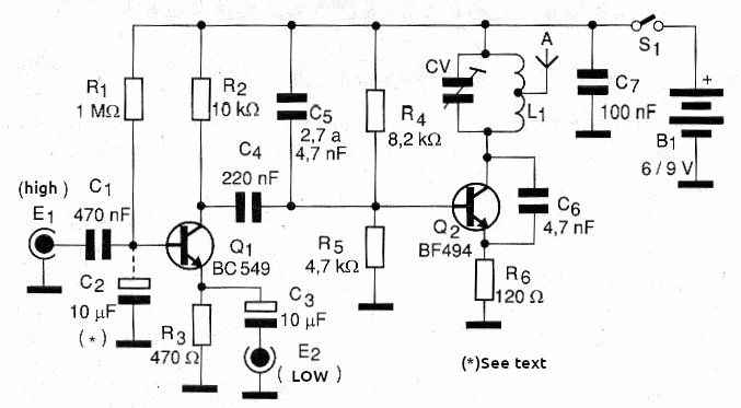
The circuit consists of two stages. The first uses a BF494 transistor or equivalent to generate a high-frequency signal in the FM band. The frequency of this signal is determined by the characteristics of the coil and the adjustment of the trimmer. This is the most critical point of the circuit, since we also connect the antenna to it. If the antenna is connected directly to the transistor collector, the circuit becomes unstable and any movement can throw it out of tune, causing the signal to escape.
A better way to achieve stability is to “match” the impedance of the circuit with the antenna, and this is achieved by connecting it to a socket on the coil. After assembling the transmitter, the reader must experiment to find the best position on the coil that results in stable operation, but in general, between the first and second coils, good performance is already achieved. The second stage of the circuit consists of an audio preamplifier with a low impedance input. This circuit matches the low impedance of most types of pickups (coil) used in musical instruments with the characteristics of the transmitter. It amplifies the signal from the pickup and applies it to the oscillator so that it can be transmitted. We also offer the possibility of using a high impedance pickup, in which case it will be connected to the second input of the circuit. This is the case of the so-called “crystals” that have a more intense signal. For these pickups, the 1 M ohm resistor should eventually be changed until a distortion-free sound is obtained, and the 10 uF capacitor (C2) should be removed from the circuit. The reader should try both possibilities to find out which type of pickup his instrument uses. The power supply comes from 4 small batteries that will last a long time since the transmitter's consumption is quite low.
ASSEMBLY
In figure 1 we have the complete diagram of the wireless guitar that uses two transistors.
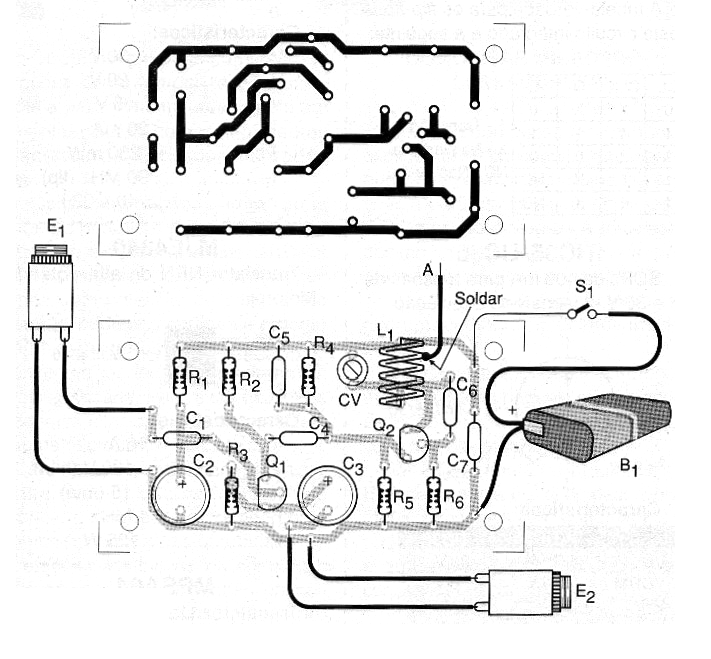
The printed circuit board for mounting the transmitter is shown in Figure 2.
The coil L1 consists of 2 + 2 turns of enameled wire with a thickness between 22 and 28 AWG, wound around a pencil as a reference (approximately 1 cm in diameter). The CV trimmer can be of any value between 20 and 50 pF of maximum capacitance. It should be adjusted so that the transmitter signal is picked up on a frequency free from the FM band. The antenna should not be touching anything. This antenna is connected to the first or second turn of the coil L1. Scrape the enameled wire where it will be soldered.
In some cases, the antenna may be only 4 or 5 cm long, if the device case is plastic and the receiver is no more than 5 meters from the musician.
The resistors are all 1/8W and the capacitors must be of the types indicated in the material list. Do not use polyester types where ceramic capacitors are recommended. The input jack J1 must be of the appropriate type for the pickup plug of the instrument used.
For power supply, we have two options: use 4 small batteries with greater autonomy and less range or use a 9 V battery with less autonomy but greater range.
Adjustment and Use
The only adjustment to be made during operation is to set the receiver to a free frequency in the FM band and adjust the CV so that the best signal from the transmitter is picked up. Try moving away from the transmitter to see how far the signal can be picked up. If the signal disappears quickly (about 2 or 3 meters), it is because you have tuned in to a “spurious” or harmonic. Re-tune the transmitter by adjusting the CV and searching for a new frequency. If instability occurs when moving the transmitter, reduce the length of the antenna or change its soldering point on coil L1. Then test the pickup on your guitar according to the configuration (high or low impedance), making changes to the circuit if necessary.
To use, simply plug the guitar pickup plug into the corresponding input and tune the receiver to the desired frequency.
There are two ways to use the device: with a stereo that already has an FM receiver or with a small FM radio whose headphone output is connected to the amplifier input, as shown in figure 3.

The circuit does not allow two units to operate simultaneously in the same location, tuned to the same frequency.
MATERIAL LIST
Semiconductors:
Q1 - BC549 or equivalent - low noise NPN transistor
Q2 - BF494 or BF495 - RF NPN transistor
Resistors: (1/8W, 5%)
R1 - 1 M ohms - brown, black, green
R2 - 10 k ohms - brown, black, orange
R3 - 470 ohms - yellow, violet, brown
R4 - 8.2 k ohms - gray, red, red
R5 - 4.7 k ohms - yellow, violet, red
R6 - 120 ohms - brown, red, brown
Capacitors:
C1 - 470 nF - ceramic or polyester
C2, C3 - 10 µF/12V - electrolytic
C4 - 220 nF - ceramic or polyester
C5 - 2.7 nF to 4.7 nF - ceramic
C6 - 4.7 or 5.6 pF - ceramic
C7 - 100 nF - ceramic
CV - common plastic or porcelain trimmer - see text
Miscellaneous:
J1, J2 - Input jacks
L1 - Coil - see text
S1 - Single switch
B1 - 6 or 9 V - 4 batteries or battery pack
A - antenna - 10 cm wire (optional)
Printed circuit board, mounting box, battery holder or battery connector, wires, solder, etc.


