The Arduino microcontrollers, such as the UNO has an internal voltage regulator that provides the 5 V it needs for its circuits and also for the outputs.
This regulator accepts inputs of 6-20 V, but in practice these limits should be observed very carefully.
Firstly a very low voltage, close to 6 V, for example, the 4 smaller batteries, may cause some feeding problems occur, mainly at the outputs.
This means that in some cases, particularly with less reliable boards, the voltage outputs can not reach the 5 V.
In the case of simple applications and non-critical, such as the lighting of LEDs, this is not a serious problem, but if we excite a TTL shield with the power of 5 V or a less sensitive circuit, problems may occur.
Thus, in practice, it is recommended that a voltage of 7 V input in most applications.
In the case of designs powered by common batteries, for example, a robot, a simple solution is to connect a support of 4 batteries in series with a second battery support, and thus to the power with 9 V, as shown in Figure 1 .

It is not recommended using 9V battery, as the power that these batteries provide is very low and not enough to power one Arduino, especially when a higher current is required in one of its outputs.
And of course, to avoid interference from the motor brushes, if they are controlled, you should use for them a separated source with current capacity according to its needs.
Medium, large common batteries or batteries in general, are the sources recommended in these cases.
Another interesting alternative is to use two batteries of mobiles of 4.5V in series.
In addition to their reduced size and weight these batteries are rechargeable and have a great current capacity which results in a good autonomy in feeding an Arduino.
We only identify their connecting pins, and make the connection as shown in Figure 2.
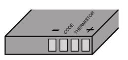
If in doubt use a multimeter to check the voltage and identify the terminals, but beware, never put in short these terminals because the intense heat generated by the current can even cause the battery to explode.
An appropriate charger will be interesting to make the work easier.
Power Sources
If the Arduino can be powered on a bench for fixed projects such as, for example, a mechanical arm, belt, door opening automation, remote control electronics, or demonstrations, a source powered by the power grid can be used.
There are many options for this.
The first is an eliminator of common batteries or AC/DC converter of 7.5 to 12 V with current from 250 mA to 1 A.
Note that the current will determine how many loads you can use. For example, for an eliminator 250 mA maximum you can feed a three loads of 50 mA, since the remainder is needed to feed the Arduino itself.
In Figure 3 we have an eraser that can be purchased at any store of electrical / electronic items.
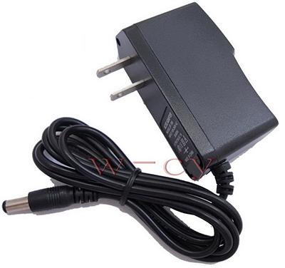
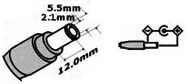
Note that the eliminator should have a 2.1 mm Arduino-compatible plug with a positive in the middle, as shown in Figure 4.
While the Arduino boards accept an input up to 20 V, we do not recommend that higher voltage than 12 V is used for a simple reason.
The amount of heat generated in the voltage regulator of the Arduino depends on the difference between the input voltage and the output multiplied by the current.
Thus, for a current of 0.5 A, for example, if the input is 12 V and the output is 5 V it will be:
The regulator will then have to dissipate a greater amount of heat, which could compromise its integrity.
And, of course, having a current capacity greater than the converter itself can be used as a source for shields, in an external power supply, provided that they support the required current.
But if the reader has components available as a small transformer, diodes and capacitors, he/she can perfectly assemble its source.
Building a Power Source
As an Arduino has an on-board voltage regulator only required to be applied on its input DC voltage from 7.5 to 12 V there is no need to use its regulated power supplies.
So a very simple source without regulation, reasonable filtering supply voltages in the indicated range, serves perfectly.
So we have many options.
In Figure 5 we have the simplest option, in fact, it is the circuit found in most eliminators or low-cost converters.
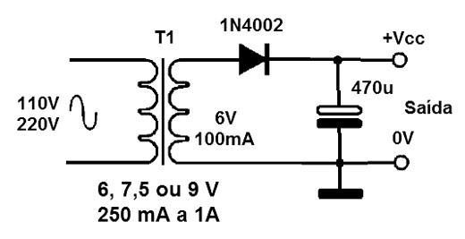
In this circuit we can use any transformer 6 to 9 V with current between 250 mA and 1 A.
See that when we use a transformer of 6 V, after the rectification with open circuit, the capacitor is charged with a voltage that corresponds to the peak of the rectified voltage that is:
With a good capacitor, this tension will not fall much in making the power of the Arduino and its operation will be normal.
With 9 V, the output voltage in open 12.6 V which is within the limits recommended for the microcontroller.
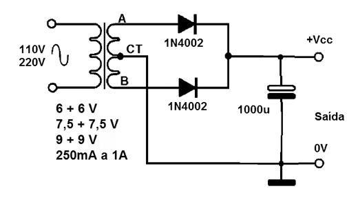
A version with better performance takes a transformer with a center plug, using two diodes, as shown in Figure 6.
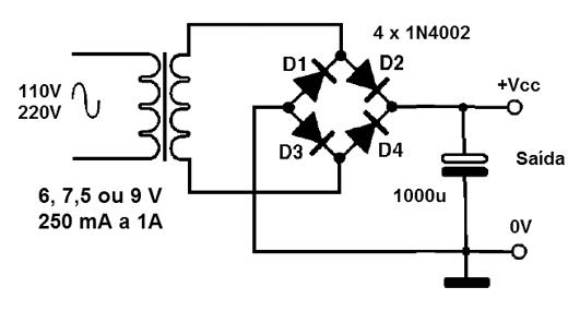
Finally, we have a source using a diode bridge (4 diodes) with a transformer from 6 to 9 V single winding and current from 250 mA to 1 A.
This source, shown in Figure 7 has a good feeding performance of a Arduino.
While it is possible, we do not recommend the use of transformerless sources.
In the shock hazard if we touch at any point of the circuit, the voltage that can appear, in case of accidental short or even touch it, is more than enough to burn the delicate components of the plate.
Likewise, to control any device powered by the power grid is recommended to always use isolated shields.
In our book Circuit Bench - Volume 30 - Shields and Interfaces there is a lot of circuits that can be used for this purpose.