Symmetric sources or power supplies are widely used in powering circuits with operational amplifiers that need both positive and negative voltages to a reference point (ground).
The typical voltages of these sources vary between 3 and 15 V and the currents are low, unless the circuits have power stages. Their currents typically range from 10 to 500 mA. Following we show simple symmetric power source circuits, one unregulated, another regulated by a zener diode, and finally one transistorized, and which can be used in most of the less critical applications that use operating amplifiers and voltage comparators.
The first has the circuit shown in Figure 1, and transformers of 5 + 5, 6 + 6, 7.5 + 7.5, 9 + 9 V and up to 12 + 12 V can be used depending on the desired voltage at the output.
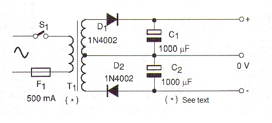
We note that the unloaded (open) voltage is the peak voltage of the secondary of the transformer, i.e., a much higher value which can reach 18 V in the case of 12 V transformers. Thus, for operational with maximum voltages of 15 V a transformer with a maximum of 9 V of secondary should be used. The maximum current of this source is given by the transformer. For this configuration we recommend a maximum current of 500 mA. The capacitors must have working voltages at least twice higher than the secondary voltage of the used transformer as they charge themselves with the peak voltage.
D1, D2 - 1N4002 - silicon rectifier diodes
T1 - Transformer - primary according to the local power line, secondary - see text
C1, C2 - 1 000 µF - electrolytic capacitors - see text
S1 - Single on/off switch
F1 - 500 mA - fuse
Miscellaneous: A printed circuit board or terminal strip, power cable, a fuse holder, a box to build the circuit, wires, weld, etc.
The second power source has a zener diode regulation and it is shown in Figure 2.
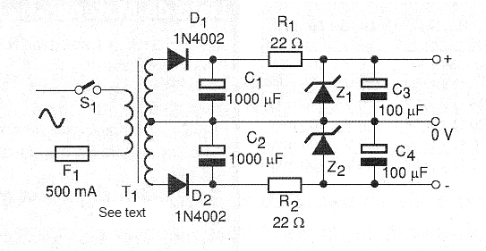
The maximum current of this source is lower, in the order of only 50 mA, and the voltage will be fixed in two most used values: 6 and 12 V. For other voltages, the zener and resistors must have their values ??changed. Figure 3 shows how we can obtain a symmetric source using a single secondary transformer.
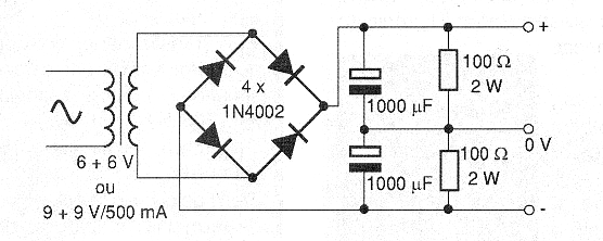
Note that for a transformer with a 12 V secondary, the source will be approximately 6 + 6 V.
D1, D2 - 1N4002 - silicon rectifier diodes
Z1, Z2 - 6 or 12 V x 1W - zener diodes according to the desired output voltage
C1, C2 - 1000 µF x 25 V - electrolytic capacitors
C3, C4 - 100 µF x 16 V - electrolytic capacitors
R1, R2 - 22 Ω x 1 W - resistors - red, red, black for 6 V or 10 Ω x 1 W - brown, black, black, for 12 V
T1 - Transformer with 12 V + 12 V of secondary from 50 mA to 300 mA - primary according to the power grid
S1 - Single switch
F1 - 500 mA - fuse
Miscellaneous:
A printed circuit board or terminal bridge, box to build the circuit, wires, weld, power cable, etc..
Transistorized Symmetrical Power Source
Using transistorized regulators with NPN and PNP transistors we can produce a symmetric source of better performance for output currents up to 500 mA. The source shown in Figure 4 has an output voltage which is determined by the zener diodes.
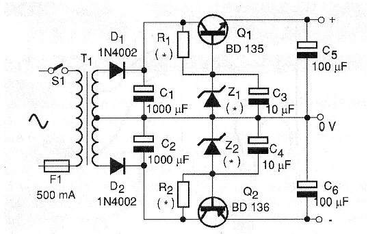
The resistors R1 and R2 have their values ??depending on the voltage of the zener diode according to the following table:
| Output Voltage | Transformer (secundary) | R1, R2 | Zener Diode |
| 6 + 6 V | 7,5 + 7,5 V | 150 ohm x 1/2 W | 6,6 V x 400 mW |
| 6 + 6 V | 9 + 9 V | 270 ohm x ½ W | 6,6 V x 400 mW |
| 6 + 6 V | 12 + 12 V | 390 ohm x ½ W | 6,6 V x 400 mW |
| 9 + 9 V | 12 + 12 V | 220 ohm x ½ W | 9,8 V x 400 mW |
| 9 + 9 V | 15 + 15 V | 470 ohm x ½ W | 9,8 V x 400 mW |
| 12 + 12 V | 15 + 15 V | 270 ohm x ½ W | 12,6 V x 400 mW |
The recommended secondary current for the transformer is 500 mA, but if smaller transformers are used the source will also work however it will provide a lower maximum current. In Figure 5 we have a suggested circuit board for this source.
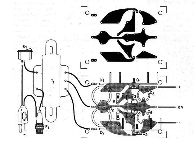
The transistors must be equipped with heat radiators and their position must be observed with care. The circuit can be built in a small plastic box, with different color terminals for the output. A LED indicator in parallel with the outputs can be added to indicate the operation. The resistor in series with this LED will be 470 ohm for a 6 V source, 560 ohm for a 9 V source and 1 k ohm for a 12 V supply.
Q1 – BD135 – NPN medium Power transistor
Q2 – BD136 – PNP médium Power transistor PNP
Z1, Z2 – Zener diodes 400 mW – acoording output voltage – see table
D1, D2 – 1N4002 – rectifier diodes
R1, R2 – see table – according voltage and transformer
C1, C2 – 1 000 µF – electrolytic capacitors
C3, C4 – 10 µF – electrolytic capacitors
C5, C6 – 100 µF – electrolytic capacitors
T1 – Transformer – see tableF1 – 500 mA – fusível
S1 – SPST
Other:
Printed circuit board or terminal struip, fuse holder, heatsink for the transistors, etc..


