Transistors are ideal elements to drive relays. With transistor amplifier stages, weak signals will be increased to the necessary level to drive a relay.
There are many ways to use transistors as relay drivers as figure 1 shows.
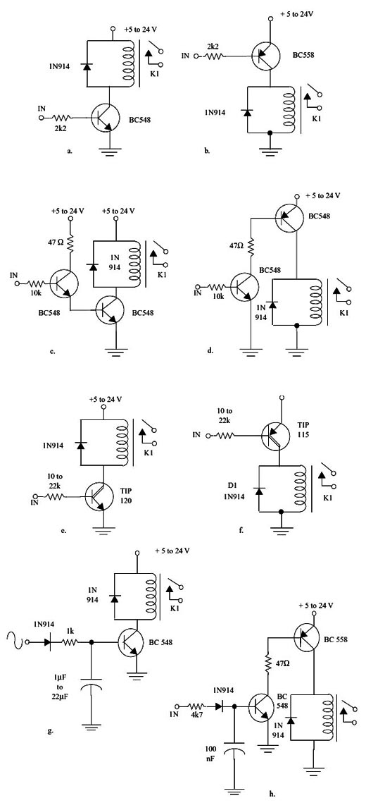
In this figure we show basic configurations where transistors bipolar common and Darlington. The caracteristics of each configuration are explained in the next lines:
(a) This is the simplest configuration that can be used to drive small sensitive relays (50 mA or less) in the voltage range between 5 ans 24 V. General purpose transistors as the ones suggested in the table at the end of this section can be used. This circuit can be driven from TTL or CMOS signal and turns on the relay with positive voltages (at the HI logic level). This circuit can be driven directly from the signal sourced by the parallel port of a PC. If relays with coil currnts between up to 500 mA must be driven the resistor is reduced to 1 k Ω and the transistor is replaced by any medium power NPN as the BD135. In this case the signal from a parallel por is not enough to drive the medium power transistor.
(b) The equivalent circuit for the one shown in (a), but using a PNP transistor is shown here. This circuit turns on the relay with a negative voltage or the LO logic level if it is used with CMOS or TTL logic. Relays with coil currents up to 50 mA and voltages between 5 and 24 V can be driven. If for power is needed to drive the relay (up to 500 mA), reduce the resistor to 1 k Ω and replace the transistor by a medium power unit as the BD136 (see table at the end of the section). In this case, the signal sourced by a parallel port of a PC is not enough to drive the circuit.
(c) If very low power signals are used to drive the circuit as the ones supplied by sensor or low gain stages, a Darlington configuration may be used. The configuration shown here can drive relays up to 50 mA. If larger coil currents are need replace the transistor Q2 by a BD135 or TIP31. This circuit turns on the relay when a positive voltage or HI logic level is applied to the input. The circuit is TTL and CMOS compatible. Low power operational amplifiers can also be used to drive this stage.
(d) Other high gain circuit but using PNP and NPN transistors (complementary) is shown here. The characteristics are the same and the PNP transistor can be replaced by a BD135 if more power is need to drive the relay (up to 500 mA).
(e) Darlington Transistors can be used to drive high power relays (coils up to 1 A) as shown here. Here we see the configuration using a NPN Darlington transistor. See the table at the end of the section for information about the suitable transistors.
(f) The PNP equivalent circuit using a Darlington transistor is shown here. See the table at the end of the section for suggestions about suitable transistors.
(g) AC signals (up to 100 kHz) can be used to drive e DC relay using a transistor. Tones from the output of an amplifier or decoder of a remote control receiver are example of sources for these signals. The circuit shown in the figure can drive a 50 mA relay from signals of 200 mVpp.
(h) This circuit can drive a relay from weak AC signals since it is more senstive than the previous..
Drive Circuits Using Other Semiconductors
SCRs, Power MOSFETs, IGBTs, and other semiconductor devices can be used to drive a relay.
Figure 2 shows some basic configurations where these devices are used.
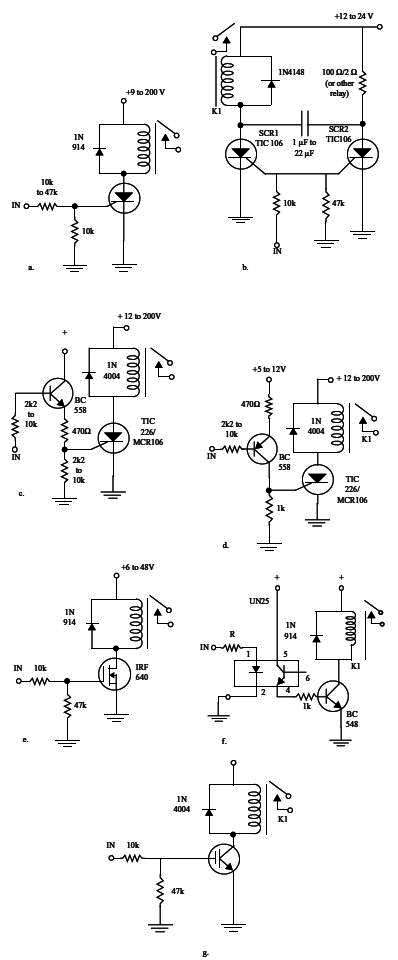
The main characteristics of each configuration are explained in the next lines:
(a) Here we show how a sensitive SCR as the ones of the 106 series can be used to drive a relay. Relays with voltages in the range from 6 V to 200 V can be used and the coil current is limited to 2 A. If relays with more than 500 mA of coil current are driven the SCR must be mounted on a heatsink. This circuit, when operating powered from a DC supply latches when a positive signal (1,8 to 2 V - 200 µA) is applied to the gate of the SCR. So, even after the trigger signal is removed the SCR remains on. To turn off the circuit it is necessary to press S1 or to cut the power supply current by a moment.
(b) This circuit shows a bistable configuration driving one or two relays using two SCRs and powered from a DC power supply. The value of C (between 1 µF and 22 µF) is chosen experimentally as function of the characteristics of the relays. The circuit changes the state when positive pulses are applied to the gates of the SCRs.
(c) Driving a SCR with a transistor is shown here. This circuit is sensitive enough to be driven from TTL, CMOS logic and also signals from the parallel port of a PC. This circuits needs only few microamperes of a positive voltage to be driven. The SCR also latches when triggering from a short pulse in the input. To turn off S1 must be pressed or the supply cut by a moment.
(d) The equivalent circuit using a PNP transistor to drive the SCR is shown here. This circuit needs only few microamperes of a negative pulse to be triggered. To turn off the same procedure described in (c) is adopted.
(e) This circuit shows how a Power MOSFET is used to drive a relay. A positive voltage of aout 2 V is need to turn on the relay. This circuit has a very high input impedance and can be driven directly from CMOS logic. Relays with voltage coils up to 48 V can be controlled by this configuration.
(f) Double isolation is provided by this circuit where an opto-coupler is used to drive a relay. This circuit is ideal for applications where the parallel por is used to drive a relay.
(g) Here we have a configuration using an IGBT to drive a relay. IGBTs have input characteristics of a Power MOSFET but control caracteristics of bipolar transistors.
Obs: how to drive relays and other loads from signals of a parallel port of a PC is found in Part 13.
Charateristics of Common relays - Table
| Type | Coil Voltage (V) | Coil Current (mA) | Coil Resistance (Ω) |
| Reed - SPST | 3 | 10 | 300 |
| Reed - SPST | 6 | 5 | 1,200 |
| Reed - SPST | 12 | 5 | 2,400 |
| Mini/DIP | 5 | 100 | 50 |
| Mini/DIP | 5 | 50 | 100 |
| Mini/DIP | 6 | 100 | 60 |
| Mini/DIP | 6 | 50 | 120 |
| Mini/DIP | 9 | 18 | 500 |
| Mini/DIP | 12 | 100 | 120 |
| Mini/DIP | 12 | 50 | 240 |
| Mini/DIP (*) | 12 | 10 | 1200 |
(*) Ultra sensitive
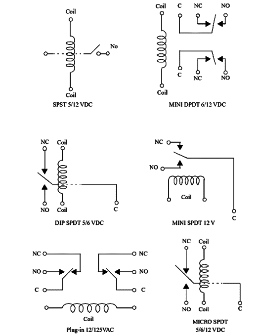
Figure 3 shows the pinout of some popular relays.