

Intercoms projects of various types receivers, sirens, warning systems, amplifiers for musical instruments and computers require good power audio amplifiers. An interesting solution is the one based on specific integrated circuits requiring few external components, have excellent efficiency and power characteristics and distortion quality.
The TDA2002 also specified as uPC2002 is one such integrated circuits. The TDA2002 can supply power up 8 Wrms or 30 Wpmpo with very few external components and has a sensitivity of only 50 mV for full power.
Many commercial devices use this module both for its ease of obtaining and its low cost. The project we give is a basic amplifier module with this amplifier and can be used as audio output stage in projects such as:
• Amplifiers for musical instruments
• Amplifier for computers
• Economic bass box (Bass Booster)
• Intercoms
• Sirens
• Warning Systems
• Communications receivers and radio
With two modules of this kind the reader may draw up a stereo system 60 Wpmpo and four modules, a 120 Wpmpo system. With the use of filters, modules can be used to amplify bass, midrange and treble in sound systems of various kinds.
The TDA2002
The TDA2002 integrated circuit is a power amplifier basically designed for applications in tape players and car stereos. Figure 1 shows the pinout of the integrated circuit.

Supply Voltage (Vs) ................ 8-18 V
Quiescent current (Is) ..................... 45-80 mA
Output power (Po)
d = 1%, RL = 2 ohm ................. 4.8 W (min)
Vs = 16 V, RL = 2 Ω ............. 10 W (typ)
Sensitivity:
Po = 0.5W, RL = 4 Ω .......... 15 mV
Po = 6 W RL = 2 ohm ............. 50 mV
Frequency Response ............. 40-15000 Hz
Voltage gain (Gv) .................. 80 dB (open loop)
HOW IT WORKS
The TDA2002 integrated circuit gathers inside all the basic components necessary for the mounting of a complete amplifier. Only the higher value capacitors are external and resistor network of R1 and R2 that determines their gain.
The relationship between the values of these components determines the voltage gain circuit which in our case was fixed to 100 times. The network of C6 and R3 is a "bootstrap", or a network that compensates for the inductive characteristics of the speaker to maintain a constant output impedance, and thus the amplifier characteristics.
The current required by the circuit at full power reaches 3.5 A, which means in this case a good source should be used as their power supply. Filtering this source is also very important. In power input have two capacitors to be mounted nearby as possible of the integrated circuit power pin.
The higher value capacitor serves as a filter for the current variations when the amplifier operates with audio signals. The lower capacitor serves to decouple the high frequency circuit components avoiding instability, since the electrolytic capacitor, for its inductive characteristics can not do it.
The load impedance influences the power, however, it can not be less than 2 Ω. With speaker impedances larger, the circuit works perfectly, but its power will be somewhat lower. The circuit includes the volume control pot but depending on the application, this control can be part of the previous blocks of the project as one with preamp tone control, etc.
ASSEMBLY
In Figure 2 we have the complete diagram of the amplifier module using the TDA2002.
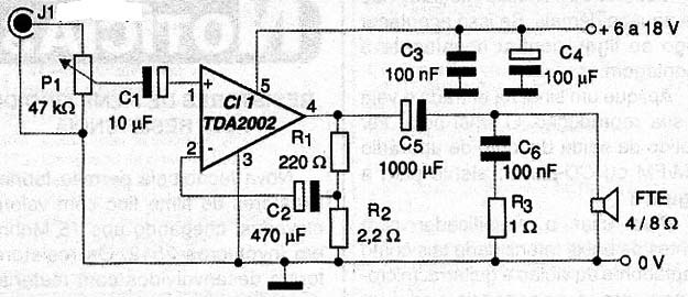
The circuit board for mounting of this amplifier is shown in Figure 3.
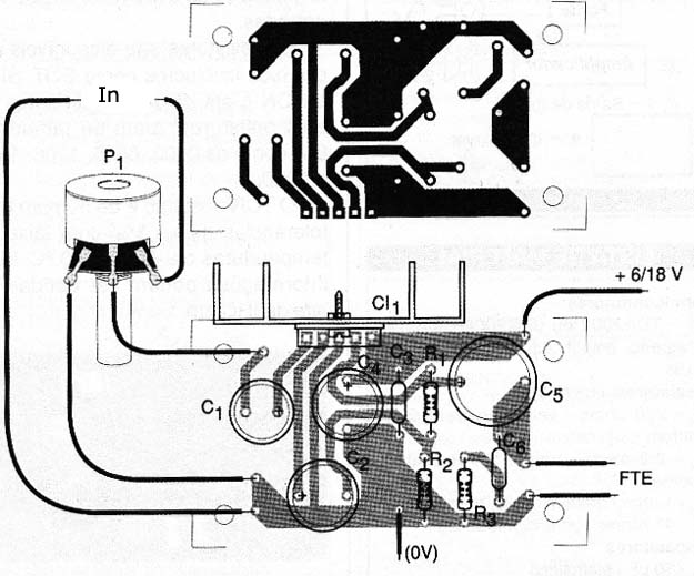
Note that the power tracks and ground, which current is more intense, as well as the speaker output should be wider. The integrated circuit should be provided with a good heatsink. In mounting the polarity of the electrolytic capacitors must be observed.
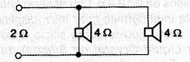
The working voltage of electrolytic capacitors should be 16 V or more and the other capacitors should be ceramic of good quality. The external speaker must be at least 10 cm in diameter with an impedance of 2 Ω to 16 Ω. To 2 Ω it is possible to connect two 4 ohm speakers in parallel, as shown in Figure 4.
The speaker must be able to handle the power of the amplifier. Remember that there is no point in spending a lot in a 100W speaker when the amplifier can only provide 8 W. The power supply to the circuit is shown in Figure 5.
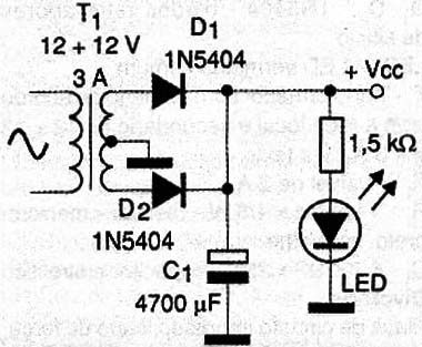
For a module, operating at a voltage of about 12 V, the transformer may have a current of 3 A or more. For more than one module to transformer secondary current must be increased proportionately. The source connection cable to the module should be short and thick to prevent any instabilities or pickup hums. The signs of the input cable must be screened for the same reason.
TEST AND USE
Check out the entire assembly before passing the test. To prove the amplifier just connect it to the power supply. Note that the integrated circuit is not too hot.
If this occur soon when connecting check the installation again. Apply a signal input and see its reproduction. The signal can be obtained source of the output of an AM / FM radio or CD player. To use the amplifier with low intensity sources such as the guitar and the guitar pickups, microphones, etc. you must use a preamp circuit.
Semiconductors:
CI-1 - or uPC2002 TDA2002 - Integrated circuit, audio power amplifier
Resistors (1 / 8W, 5%)
R1 - 220 Ω - red, red, brown
R2 - 2.2 Ω - red, red, gold
R3 - 1 ohm - brown, black, gold
P1 - 47 k Ω - log pot
Capacitors:
C1 - 10 µF - Electrolytic
C2 - 470 µF - Electrolytic
C3, C6 - 100 nF - Ceramic
C4 - 100 µF - Electrolytic
C5 - 1000 µF - Electrolytic
Miscellaneous:
FTE - High - speaker from 2 to 8 Ω - see text
Printed circuit board, heatsink to the integrated circuit, shielded cable input jack, wire, welding.
Material For Source:
D1, D2 - 1N5404 - silicon rectifier diodes
LED1 - LED, common red
T1 - with primary transformer according to the local line and secondary of 12 + 12 V x 3 - see text
F1 – 2A - fuse
R1 - 1k ohm x 1/8 W - resistor - brown, black, red
C1 - 4700 µF x 25 V - Electrolytic Capacitor
Miscellaneous:
Printed circuit board, power cable, support for the fuse, wire, solder, etc..


