

The project is based on the Texas Instruments TL051 integrated circuit consisting of an operational amplifier with input high voltage JFET transistor, and bipolar transistors in the other stages.
Among the important characteristics of this integrated circuit we emphasize that the manufacturing process used allows low initial offset voltages to be achieved due to the presence of an on-chip zener that can be adjusted and also due to the low offset voltage variation with the voltage and over time.
Devices with suffix C operate in the temperature range from 0 to 70 degrees Celsius, while those with suffix I operate from -40 to + 85 ° C. For those of suffix M, which correspond to the military range, operating temperatures range are from -55 to + 125ºC.
Other important features of the TL051 are as follows:
* Maximum offset voltage: 800 ?V
* High growth rate: 19.8 V/? s (tip at 25 ° C)
* Total harmonic distortion: 0.002% for Rl = 2k Ω
* Low voltage of noise: 18 nV/Hz at 1 kHz
* Low current of polarization: 30 pA (tip)
In Figure 1 we have the TL051 integrated circuit pin.

THE CIRCUIT
In Figure 2 we have the complete phase meter diagram suggested by Texas Instruments on the TL051 Data Sheet itself.

As explained in the introduction, the output voltage will be 10 mV for each degree of lag of the signals applied at inputs Va and Vb.
The input frequencies of Va and Vb must be equal.
Operational amplifiers U1a and U1b function as comparators by converting the input sinusoidal signals to square outputs of +/- 5V amplitude.
The voltage dividers formed by the 100 k resistors then provide the logical values for the flip-flops which correspond to the integrated circuits U2a and U2b.
U2 consists of a double J-K 7474 (HC109) flip-flop and is intended to generate a signal whose frequency is half the frequency of the input signals.
In this circuit, the pulse duration generated by U2a ranges from zero to half the period of the input signal, where zero corresponds to a zero phase delay between Va and Vb, and half of the period corresponds to an interval between Vb and Va of 360 degrees.
The output pulses of U2a makes the logic switch U3 (4066) to switch on by driving U4 (TL051), which is configured as an integrator. The integration constant is basically determined by the capacitors C1 and C2.
When the output of U2a approaches a square waveform, U4 has an output of approximately 2.5 V.
The integrated circuit U5 (TL051) operates as a non-inverting amplifier with gain of 1.44 times, so as to obtain a scale from 0 to 3.6 V for the lag intervals from 0 to 360 degrees.
The resistors R8 and R10 determine the output gain and the zero adjustment respectively. The circuit shown may operate in a frequency range from 100 Hz to 100 kHz.
APPLICATIONS
An instrument which can be easily projected from this block is shown in Figure 3.
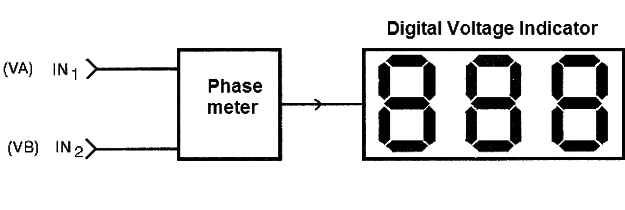
The phase meter signals are applied to a 3-digit digital voltage indicator, set to operate on a 0 to 3.6 V scale.
This way, it is possible to measure sine-wave angles of sinusoidal signals from the power grid (or from another source up to 10 kHz) with a resolution of 1 degree. With a 4-digit display we can go beyond and have a precision of 0.1 degree.
ASSEMBLY
As it is a constructive block that must be part of a specific design, the printed circuit board must be designed according to this design.
However, for initial tests the circuit can be easily built in a contact array, considering that it is not critical.
Semiconductors
U1 - TLC3702 - integrated circuit - comparator
U2 - 74HC109 - integrated circuit - J-K flip-flop
U3 - 4066 - integrated circuit - digital CMOS switch
U4, U5 - TL051 - integrated circuits - operational amplifiers
Resistors: (1/8W, 5%)
R1, R2, R3, R4 -100 k ohm
R5, R6, R7 - 10K ohm
R8 - 50 k ohm - trimpot
R9 -20k ohm
R10 - 10 k ohm - trimpot
Capacitors:
C1, C2 - 0.016 ?F
Miscellaneous:
Source, printed circuit board, wires, welder, etc.


